Digital-to-analog converter (DAC) RM0351
542/1693 DocID024597 Rev 3
17.3 DAC functional description
17.3.1 DAC block diagram
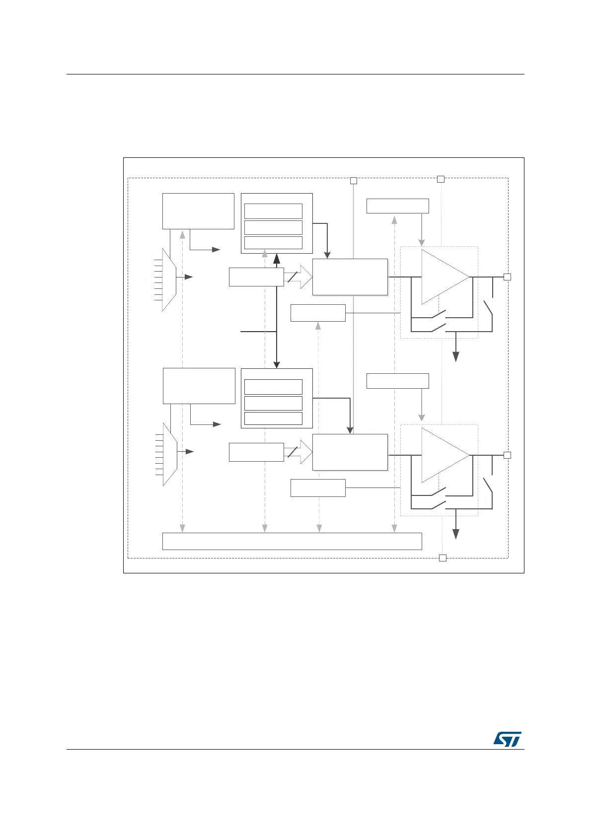
Figure 129. DAC channel block diagram
1. The output mode controller switch between the normal mode in buffer/unbuffer configuration and the
sample&hold mode
The DAC includes :
• Two output channels
• The DAC_OUTx can be disconnected from output pin and used as ordinary GPIO
• The DAC_OUTx can used internal pin connection to on-chip peripherals such as
comparators and OPAMPs.
• DAC output channel buffered or non buffered
• Sample and hold block and registers using LSI clock source and operational in STOP
mode for static conversion
06Y9
sZ&н
s
KŶͲĐŚŝƉ
WĞƌŝƉŚĞƌĂůƐ
džͺKhdϭ
ƵĨĨĞƌϭ
ĐŽŶǀĞƌƚĞƌϭ
džͺKhdϮ
ƵĨĨĞƌϮ
s^^
ϭϮͲďŝƚ
DKϭďŝƚƐ
d^DW>ϭ
d,K>ϭ
dZ&Z^,ϭ
^ĂŵƉůĞΘ,ŽůĚZĞŐŝƐƚĞƌƐ
KdZ/DϭϱϬďŝƚƐ
ŽŶƚƌŽůƌĞŐŝƐƚĞƌƐ
ΘůŽŐŝĐŚĂŶŶĞůϭ
ϭϮͲďŝƚ
>^/ĐůŽĐŬ
d^>ϭϮϬ
ďŝƚƐ
DͺZĞƋƵĞƐƚ
d/DϲͺdZ/'
d/DϴͺdZ/'
d/DϳͺdZ/'
KŶͲĐŚŝƉ
WĞƌŝƉŚĞƌĂůƐ
d/DϱͺdZ/'
d/DϮͺdZ/'
d/DϰͺdZ/'
yd/ϵͺdZ/'
^tͺdZ/'
dZ/'
d^>ϮϮϬ
ďŝƚƐ
DͺZĞƋƵĞƐƚ
d/DϲͺdZ/'
d/DϴͺdZ/'
d/DϳͺdZ/'
d/DϱͺdZ/'
d/DϮͺdZ/'
d/DϰͺdZ/'
yd/ϵͺdZ/'
^tͺdZ/'
dZ/'
KĨĨƐĞƚĐĂůŝďƌĂƚŝŽŶ
WϭƵƐ
džͺKZϮ
ŽŶƚƌŽůƌĞŐŝƐƚĞƌƐ
ΘůŽŐŝĐŚĂŶŶĞůϮ
džͺKZϭ
^ĂŵƉůĞΘ,ŽůĚZĞŐŝƐƚĞƌƐ
d^DW>Ϯ
d,K>Ϯ
dZ&Z^,Ϯ
ĐŽŶǀĞƌƚĞƌϮ
DKϮďŝƚƐ
KdZ/DϮϱϬďŝƚƐ
KĨĨƐĞƚĐĂůŝďƌĂƚŝŽŶ

 Loading...


