Advanced encryption standard hardware accelerator (AES) RM0351
734/1693 DocID024597 Rev 3
forced to CTR decryption mode if the software writes MODE[1:0] = 11 and CHMOD[2:0]
= 010.
3. Select key length 128-bit or 256-bit via KEYSIZE bits configuration in AES_CR register.
4. Write the AES_KEYRx register with the encryption key. Write the AES_IVRx register if
the CBC mode is selected.
5. Enable the AES by setting the EN bit in the AES_CR register.
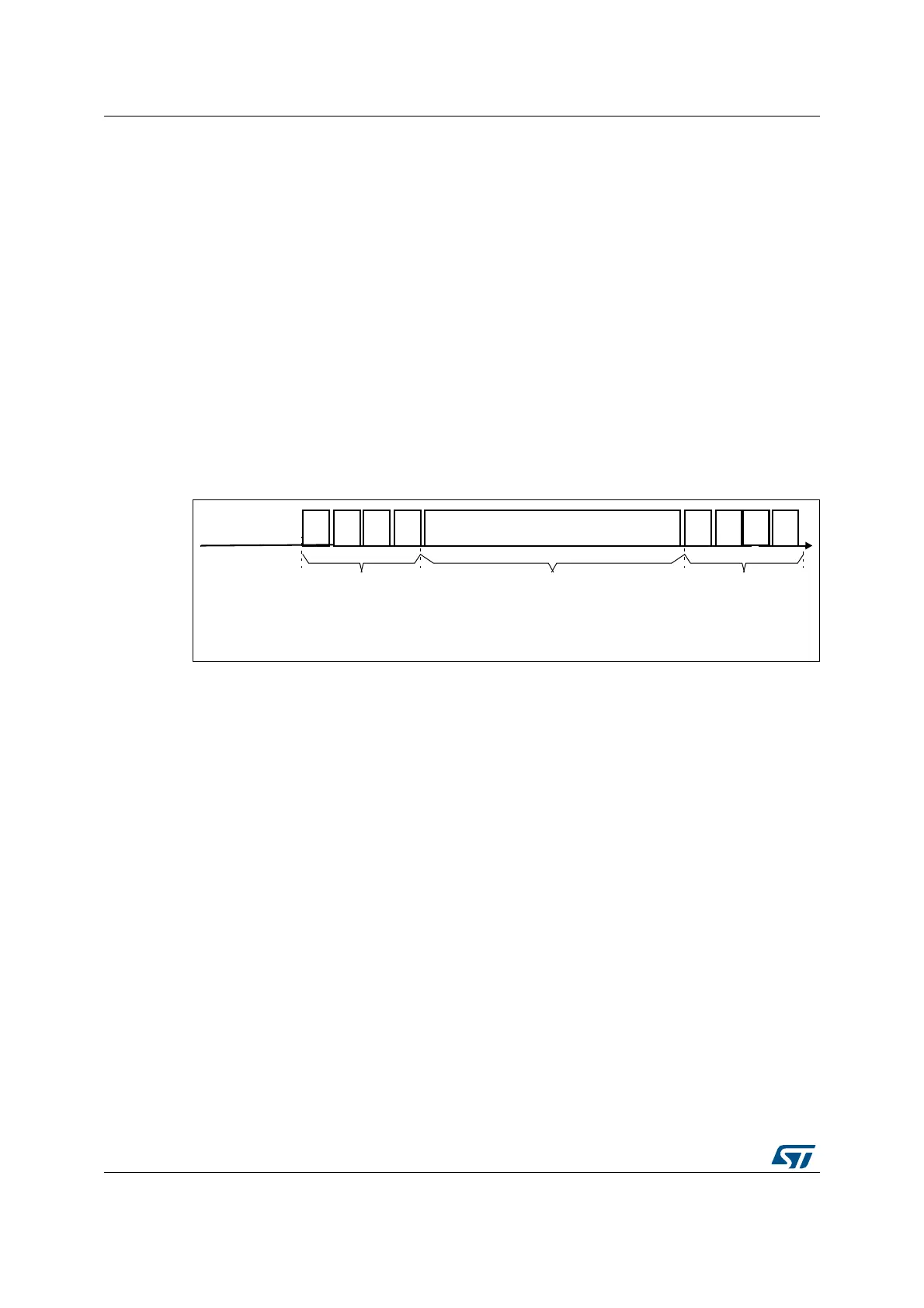
6. Write the AES_DINR register 4 times to input the cipher text (MSB first) as shown in
Figure 185: Mode 4: key derivation and decryption with 128-bit key length.
7. Wait until the CCF flag is set in the AES_SR register.
8. Read the AES_DOUTR register 4 times to get the plain text (MSB first) as shown in
Figure 185: Mode 4: key derivation and decryption with 128-bit key length.
9. Repeat steps 6, 7, 8 to process all the blocks with the same encryption key.
Note: The AES_KEYRx registers contain the encryption key during all phases of the processing,
No derivation key is stored in these registers. The derivation key starting from the encryption
key is stored internally in the AES without storing a copy in the AES_KEYRx registers.
Figure 185. Mode 4: key derivation and decryption with 128-bit key length
25.10 AES DMA interface
The AES accelerator provides an interface to connect to the DMA controller.
The DMA must be configured to transfer words.
The AES can be associated with two distinct DMA request channels:
• A DMA request channel for the inputs: When the DMAINEN bit is set in the AES_CR
register, the AES initiates a DMA request (AES_IN) during the INPUT phase each time
it requires a word to be written to the AES_DINR register. The DMA channel must be
configured in memory-to-peripheral mode with 32-bit data size.
• A DMA request channel for the outputs: When the DMAOUTEN bit is enabled, the AES
initiates a DMA request (AES_OUT) during the OUTPUT phase each time it requires a
word to be read from the AES_DOUTR register. The DMA channel must be configured
in peripheral-to-memory mode with a data size equal to 32-bit.
Four DMA requests are asserted for each phase, these are described in Figure 186 and
Figure 187.
DMA requests are generated until the AES is disabled. So, after the data output phase at
the end of processing a 128-bit data block, the AES switches automatically to a new data
input phase for the next data block if any.
72
#4
7!)45.4),
FLAG##&
040,!).4%847ORDS0404
#4#90(%24%847ORDS#4#4
72
#4
72
#4
72
#4
).0540(!3%
72)4%/0%2!4)/.3
).4/!%3?$).;=
2$
04
2$
04
2$
04
/540540(!3%
2%!$/0%2!4)/.3
/&!%3?$/54;=
#/-054!4)/.0(!3%
-3"
"3,"3-"3,
2$
04
-36