DocID024597 Rev 3 411/1693
RM0351 Quad-SPI interface (QUADSPI)
425
FSIZE[4:0] in the QUADSPI_DCR): this will set the TEF and an interrupt is generated if
enabled.
• Also in indirect mode, if the address plus the data length exceeds the Flash memory
size, TEF will be set as soon as the access is triggered.
• In memory-mapped mode, when an out of range access is done by an AHB master or
when the QUADSPI is disabled: this will generate an AHB error as a response to the
faulty AHB request.
• When an AHB master is accessing the memory mapped space while the memory
mapped mode is disabled: this will generate an AHB error as a response to the faulty
AHB request.
15.3.13 QUADSPI busy bit and abort functionality
Once the QUADSPI starts an operation with the Flash memory, the BUSY bit is
automatically set in the QUADSPI_SR.
In indirect mode, the BUSY bit is reset once the QUADSPI has completed the requested
command sequence and the FIFO is empty.
In automatic-polling mode, BUSY goes low only after the last periodic access is complete,
due to a match when APMS = 1, or due to an abort.
After the first access in memory-mapped mode, BUSY goes low only on a timeout event or
on an abort.
Any operation can be aborted by setting the ABORT bit in the QUADSPI_CR. Once the
abort is completed, the BUSY bit and the ABORT bit are automatically reset, and the FIFO
is flushed.
Note: Some Flash memories might misbehave if a write operation to a status registers is aborted.
15.3.14 nCS behavior
By default, nCS is high, deselecting the external Flash memory. nCS falls before an
operation begins and rises as soon as it finishes.
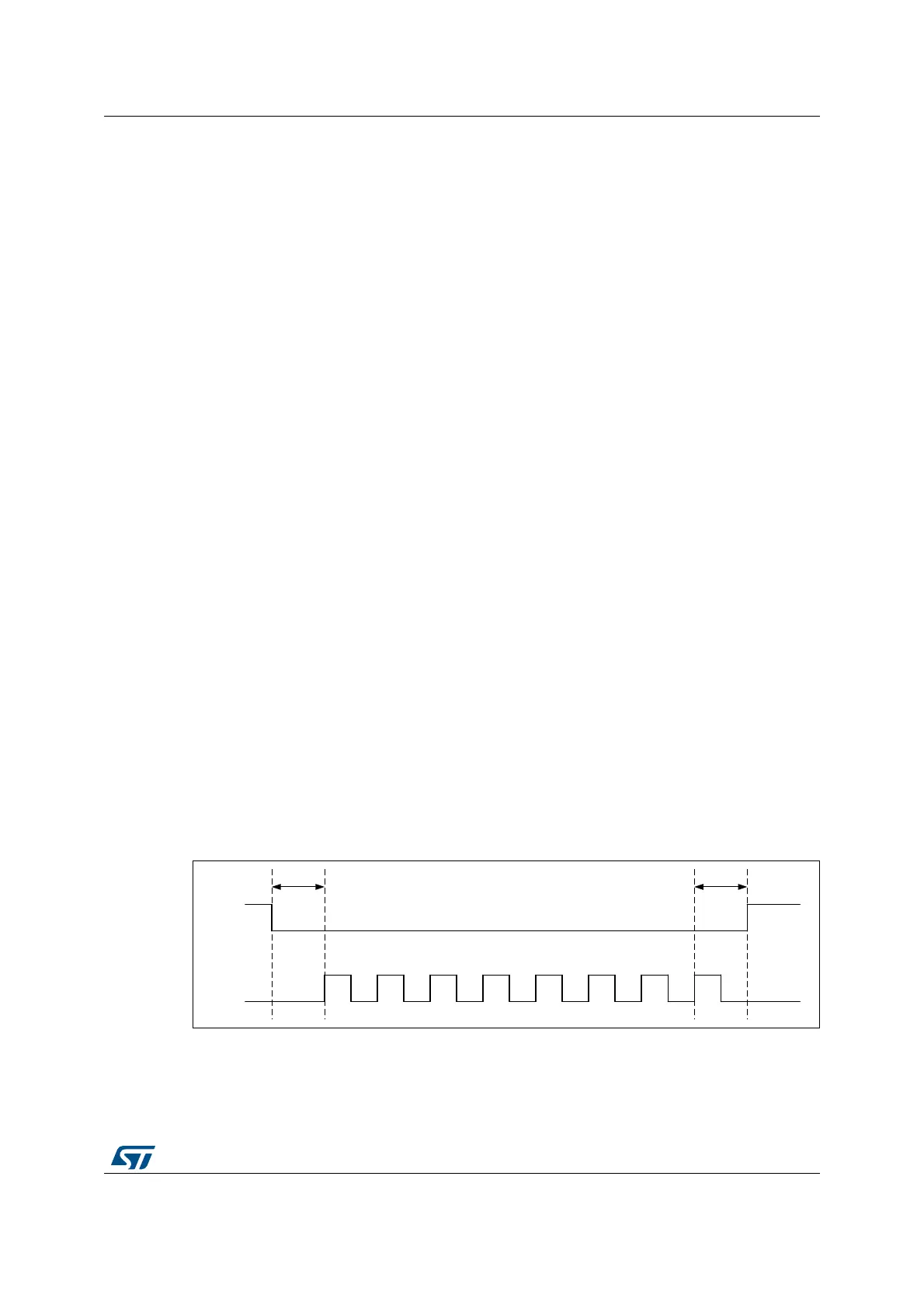
When CKMODE = 0 (“mode0”, where CLK stays low when no operation is in progress) nCS
falls one CLK cycle before an operation first rising CLK edge, and nCS rises one CLK cycle
after the operation final rising CLK edge, as shown in Figure 54.
Figure 54. nCS when CKMODE = 0 (T = CLK period)
When CKMODE=1 (“mode3”, where CLK goes high when no operation is in progress) and
DDRM=0 (SDR mode), nCS still falls one CLK cycle before an operation first rising CLK
edge, and nCS rises one CLK cycle after the operation final rising CLK edge, as shown in
Figure 55.

 Loading...


