Advanced-control timers (TIM1/TIM8) RM0351
818/1693 DocID024597 Rev 3
Bits 2:0 SMS: Slave mode selection
When external signals are selected the active edge of the trigger signal (TRGI) is linked to the
polarity selected on the external input (see Input Control register and Control Register
description.
0000: Slave mode disabled - if CEN = ‘1’ then the prescaler is clocked directly by the internal
clock.
0001: Encoder mode 1 - Counter counts up/down on TI1FP1 edge depending on TI2FP2
level.
0010: Encoder mode 2 - Counter counts up/down on TI2FP2 edge depending on TI1FP1
level.
0011: Encoder mode 3 - Counter counts up/down on both TI1FP1 and TI2FP2 edges
depending on the level of the other input.
0100: Reset Mode - Rising edge of the selected trigger input (TRGI) reinitializes the counter
and generates an update of the registers.
0101: Gated Mode - The counter clock is enabled when the trigger input (TRGI) is high. The
counter stops (but is not reset) as soon as the trigger becomes low. Both start and stop of
the counter are controlled.
0110: Trigger Mode - The counter starts at a rising edge of the trigger TRGI (but it is not
reset). Only the start of the counter is controlled.
0111: External Clock Mode 1 - Rising edges of the selected trigger (TRGI) clock the counter.
1000: Combined reset + trigger mode - Rising edge of the selected trigger input (TRGI)
reinitializes the counter, generates an update of the registers and starts the counter.
Codes above 1000: Reserved.
Note: The gated mode must not be used if TI1F_ED is selected as the trigger input
(TS=’100’). Indeed, TI1F_ED outputs 1 pulse for each transition on TI1F, whereas the
gated mode checks the level of the trigger signal.
Note: The clock of the slave timer must be enabled prior to receive events from the master
timer, and must not be changed on-the-fly while triggers are received from the master
timer.
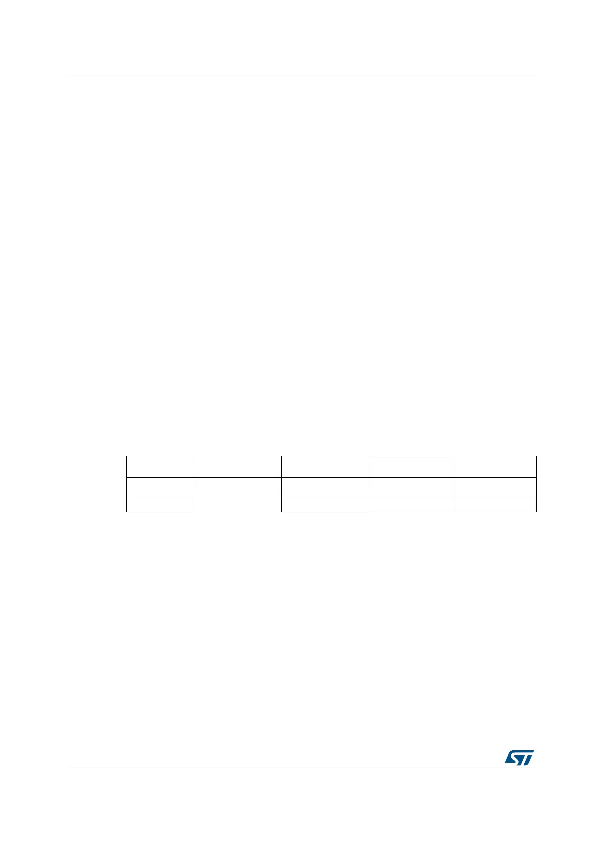
Table 148. TIMx internal trigger connection
Slave TIM ITR0 (TS = 000) ITR1 (TS = 001) ITR2 (TS = 010) ITR3 (TS = 011)
TIM1 TIM15 TIM2 TIM3 TIM4
TIM8 TIM1 TIM2 TIM4 TIM5

 Loading...


