DocID024597 Rev 3 777/1693
RM0351 Advanced-control timers (TIM1/TIM8)
856
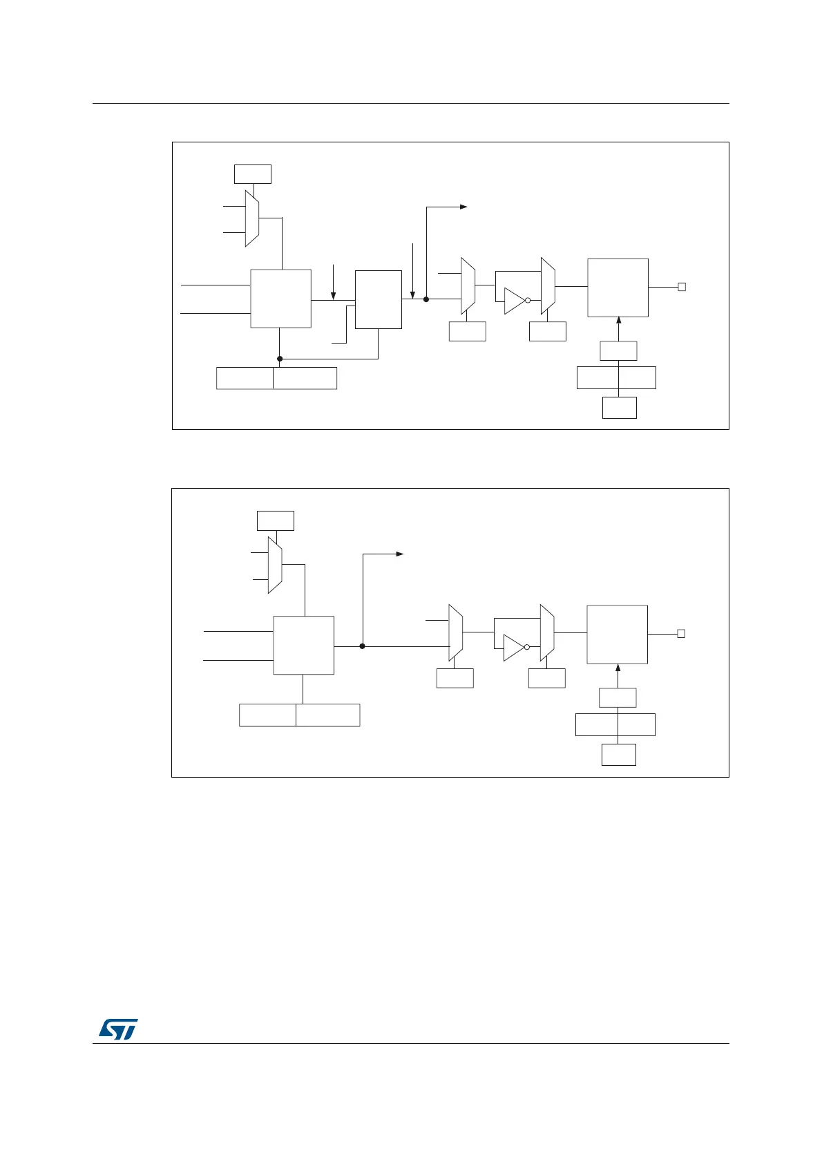
Figure 220. Output stage of capture/compare channel (channel 4)
Figure 221. Output stage of capture/compare channel (channel 5, idem ch. 6)
1. Not available externally.
The capture/compare block is made of one preload register and one shadow register. Write
and read always access the preload register.
In capture mode, captures are actually done in the shadow register, which is copied into the
preload register.
In compare mode, the content of the preload register is copied into the shadow register
which is compared to the counter.
06Y9
2XWSXW
PRGH
FRQWUROOHU
&17!&&5
&17 &&5
7,0B&&05
2&0>@
&&3
7,0B&&(5
2XWSXW
HQDEOH
FLUFXLW
2&
&&(
7,0B&&(5
7RWKHPDVWHU
PRGHFRQWUROOHU
2&5()
2&&(
&&(
7,0B&&(5
µ
7,0B%'75
266,
02(
2,6
7,0B&5
RFUHIBFOUBLQW
(75)
1&
2&&6
7,0[B60&5
2XWSXW
VHOHFWRU
2&5()
2&5()&
06Y9
2XWSXW
PRGH
FRQWUROOHU
&17!&&5
&17 &&5
7,0B&&05
2&0>@
&&3
7,0B&&(5
2XWSXW
HQDEOH
FLUFXLW
2&
&&(
7,0B&&(5
7RWKHPDVWHU
PRGHFRQWUROOHU
2&5()
2&&(
&&(
7,0B&&(5
µ
7,0B%'75
266,
02(
2,6
7,0B&5
RFUHIBFOUBLQW
(75)
1&
2&&6
7,0[B60&5

 Loading...


