Analog-to-digital converters (ADC) RM0351
474/1693 DocID024597 Rev 3
16.3.28 Analog window watchdog (AWD1EN, JAWD1EN, AWD1SGL,
AWD1CH, AWD2CH, AWD3CH, AWD_HTx, AWD_LTx, AWDx)
The three AWD analog watchdogs monitor whether some channels remain within a
configured voltage range (window).
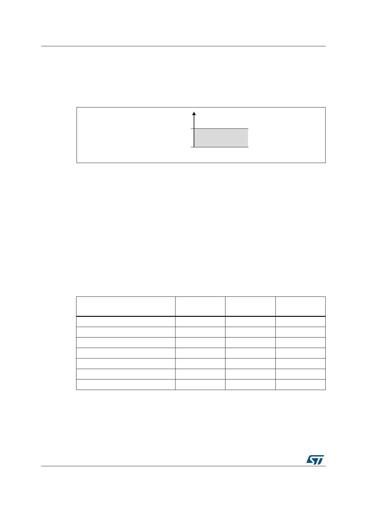
Figure 98. Analog watchdog’s guarded area
AWDx flag and interrupt
An interrupt can be enabled for each of the 3 analog watchdogs by setting AWDxIE in the
ADCx_IER register (x=1,2,3).
AWDx (x=1,2,3) flag is cleared by software by writing 1 to it.
The ADC conversion result is compared to the lower and higher thresholds before
alignment.
Description of analog watchdog 1
The AWD analog watchdog 1 is enabled by setting the AWD1EN bit in the ADCx_CFGR
register. This watchdog monitors whether either one selected channel or all enabled
channels
(1)
remain within a configured voltage range (window).
Table 92 shows how the ADCx_CFGR registers should be configured to enable the analog
watchdog on one or more channels.
Table 92. Analog watchdog channel selection
The AWD1 analog watchdog status bit is set if the analog voltage converted by the ADC is
below a lower threshold or above a higher threshold.
Channels guarded by the analog
watchdog
AWD1SGL bit AWD1EN bit JAWD1EN bit
None x 0 0
All injected channels 0 0 1
All regular channels 0 1 0
All regular and injected channels 0 1 1
Single
(1)
injected channel
1. Selected by the AWD1CH[4:0] bits. The channels must also be programmed to be converted in the
appropriate regular or injected sequence.
101
Single
(1)
regular channel 1 1 0
Single
(1)
regular or injected channel 1 1 1
DL
$QDORJYROWDJH
+LJKHUWKUHVKROG
/RZHUWKUHVKROG
*XDUGHGDUHD
+75
/75