DocID024597 Rev 3 1365/1685
RM0351 Single Wire Protocol Master Interface (SWPMI)
1392
40.3 SWPMI functional description
40.3.1 SWPMI block diagram
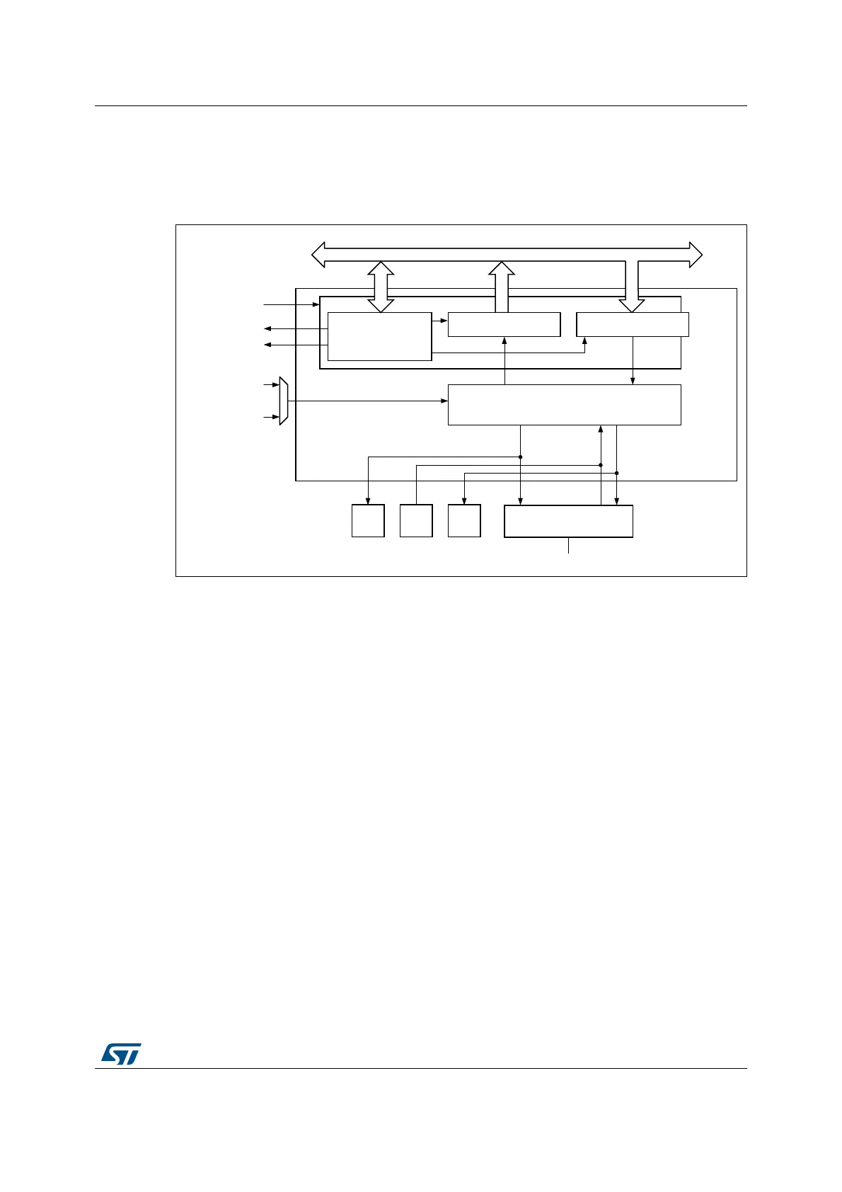
Figure 454. SWPMI block diagram
Refer to the bit SWPMI1SEL in Section 6.4.28: Peripherals independent clock configuration
register (RCC_CCIPR) to select the SWPCLK (SWPMI core clock source).
Note: In order to support the exit from Stop mode by a RESUME by slave, it is mandatory to select
HSI16 for SWPCLK. If this feature is not required, PCLK1 can be selected, and SWPMI
must be disabled before entering the Stop mode.
40.3.2 SWP initialization and activation
The initialization and activation will set the SWPMI_IO state from low to high. The procedure
is the following:
1. configure the SWP_CLASS bit in SWPMI_OR register according to the V
DD
voltage
(3 V or 1.8 V),
2. configure SWPMI_IO as alternate function (refer to Section 7: General-purpose I/Os
(GPIO)) to enable the SWPMI_IO transceiver,
3. wait for at least 20 microseconds,
4. set SWPACT bit in SWPMI_CR register to ACTIVATE the SWP i.e. to move from
DEACTIVATED to SUSPENDED.
40.3.3 SWP bus states
The SWP bus can have the following states: DEACTIVATED, SUSPENDED, ACTIVATED.
069
6:30,FRUH
6:30,B,2
3&/.
6:3&/.
'0$UHTXHVWV
3&/.
+6,
&RQWURO6WDWXV
UHJLVWHUV
6:3EXV
6:30,
6:30,B7;6:30,B5;
,QWHUUXSW
6:30,B6863(1'
*3,2*3,2*3,2
ELW$3%EXV
6:30,B7'56:30,B5'5

 Loading...


