DocID024597 Rev 3 1289/1685
RM0351 Serial peripheral interface (SPI)
1317
completed, the active slave select signal is released and the node mastering the bus
temporary returns back to passive slave mode waiting for next session start.
If potentially both nodes raised their mastering request at the same time a bus conflict event
appears (see mode fault MODF event). Then the user can apply some simple arbitration
process (e.g. to postpone next attempt by predefined different time-outs applied at both
nodes).
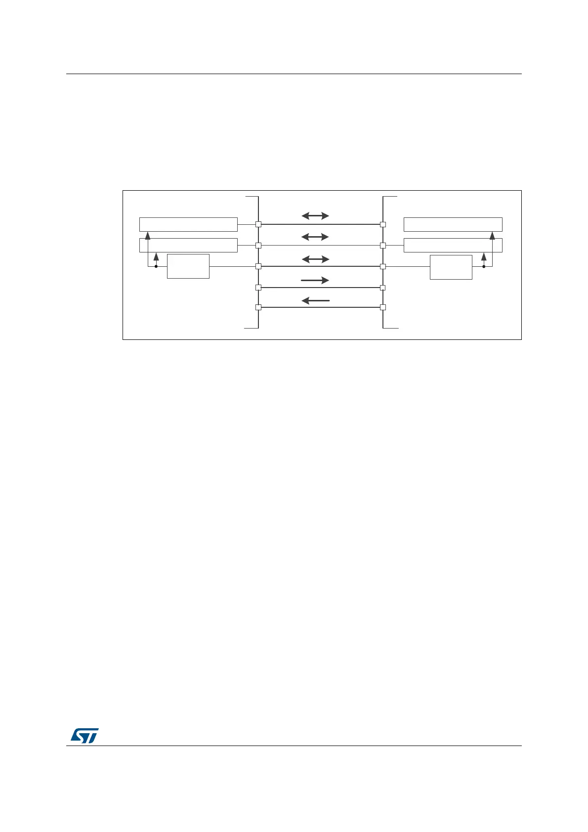
Figure 425. Multi-master application
1. The NSS pin is configured at hardware input mode at both nodes. Its active level enables the MISO line
output control as the passive node is configured as a slave.
38.4.5 Slave select (NSS) pin management
In slave mode, the NSS works as a standard “chip select” input and lets the slave
communicate with the master. In master mode, NSS can be used either as output or input.
As an input it can prevent multimaster bus collision, and as an output it can drive a slave
select signal of a single slave.
Hardware or software slave select management can be set using the SSM bit in the
SPIx_CR1 register:
• Software NSS management (SSM = 1): in this configuration, slave select information
is driven internally by the SSI bit value in register SPIx_CR1. The external NSS pin is
free for other application uses.
• Hardware NSS management (SSM = 0): in this case, there are two possible
configurations. The configuration used depends on the NSS output configuration
(SSOE bit in register SPIx_CR1).
– NSS output enable (SSM=0,SSOE = 1): this configuration is only used when the
MCU is set as master. The NSS pin is managed by the hardware. The NSS signal
is driven low as soon as the SPI is enabled in master mode (SPE=1), and is kept
low until the SPI is disabled (SPE =0). A pulse can be generated between
continuous communications if NSS pulse mode is activated (NSSP=1). The SPI
cannot work in multimaster configuration with this NSS setting.
– NSS output disable (SSM=0, SSOE = 0): if the microcontroller is acting as the
master on the bus, this configuration allows multimaster capability. If the NSS pin
is pulled low in this mode, the SPI enters master mode fault state and the device is
automatically reconfigured in slave mode. In slave mode, the NSS pin works as a
standard “chip select” input and the slave is selected while NSS line is at low level.
5[7[VKLIWUHJLVWHU
7[5[VKLIWUHJLVWHU 7[5[VKLIWUHJLVWHU
5[7[VKLIWUHJLVWHU
63,FORFN
JHQHUDWRU
0DVWHU
6ODYH
DĂƐƚĞƌ
;^ůĂǀĞͿ
0,62
026,
6&.
166
0,62
026,
6&.
166
06Y9
63,FORFN
JHQHUDWRU
*3,2
*3,2

 Loading...


