Infrared interface (IRTIM) RM0351
1046/1693 DocID024597 Rev 3
31 Infrared interface (IRTIM)
An infrared interface (IRTIM) for remote control is available on the device. It can be used
with an infrared LED to perform remote control functions.
It uses internal connections with TIM16 and TIM17 as shown in Figure 347.
To generate the infrared remote control signals, the IR interface must be enabled and TIM16
channel 1 (TIM16_OC1) and TIM17 channel 1 (TIM17_OC1) must be properly configured to
generate correct waveforms.
The infrared receiver can be implemented easily through a basic input capture mode.
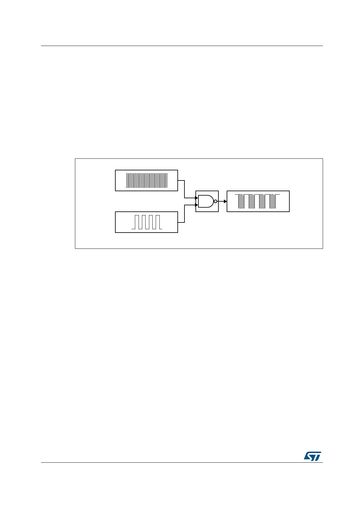
Figure 347. IR internal hardware connections with TIM16 and TIM17
All standard IR pulse modulation modes can be obtained by programming the two timer
output compare channels.
TIM17 is used to generate the high frequency carrier signal, while TIM16 generates the
modulation envelope.
The infrared function is output on the IR_OUT pin. The activation of this function is done
through the GPIOx_AFRx register by enabling the related alternate function bit.
The high sink LED driver capability (only available on the PB9 pin) can be activated through
the I2C_PB9_FMP bit in the SYSCFG_CFGR1 register and used to sink the high current
needed to directly control an infrared LED.
069
7,0B&+
7,0B&+
,57,0
,5B287

 Loading...


