DocID024597 Rev 3 1263/1693
RM0351 Low-power universal asynchronous receiver transmitter (LPUART)
1282
37.4.9 RS232 Hardware flow control and RS485 Driver Enable
using LPUART
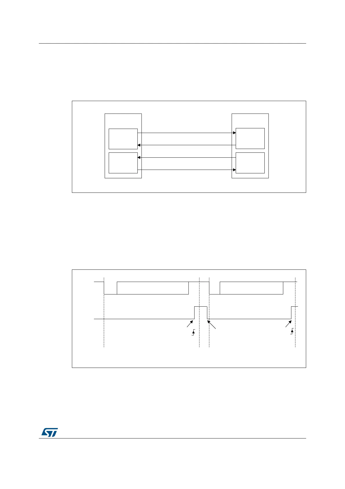
It is possible to control the serial data flow between 2 devices by using the CTS input and
the RTS output. The Figure 404 shows how to connect 2 devices in this mode:
Figure 416. Hardware flow control between 2 LPUARTs
RS232 RTS and CTS flow control can be enabled independently by writing the RTSE and
CTSE bits respectively to 1 (in the LPUART_CR3 register).
RS232 RTS flow control
If the RTS flow control is enabled (RTSE=1), then RTS is asserted (tied low) as long as the
LPUART receiver is ready to receive a new data. when the receive register is full, RTS is de-
asserted, indicating that the transmission is expected to stop at the end of the current frame.
Figure 405 shows an example of communication with RTS flow control enabled.
Figure 417. RS232 RTS flow control
RS232 CTS flow control
If the CTS flow control is enabled (CTSE=1), then the transmitter checks the CTS input
before transmitting the next frame. If CTS is asserted (tied low), then the next data is
transmitted (assuming that data is to be transmitted, in other words, if TXE=0), else the
06Y9
7;FLUFXLW
/38$57
7;
5;FLUFXLW
5;FLUFXLW
/38$57
7;FLUFXLW
7;
&76
&76
576
5;
576
5;
06Y9
6WDUW
ELW
6WDUW
ELW
6WRS
ELW
,GOH
6WRS
ELW
5;
576
'DWDUHDG
'DWDFDQQRZEHWUDQVPLWWHG
5;1(
5;1(
'DWD 'DWD

 Loading...


