Advanced-control timers (TIM1/TIM8) RM0351
796/1693 DocID024597 Rev 3
OCREF_CLR_INPUT can be selected between the OCREF_CLR input and ETRF (ETR
after the filter) by configuring the OCCS bit in the TIMx_SMCR register.
The OCREF_CLR input is not connected (NC) in this product. The OCCS bit must be set to
work in OCxREF clearing mode.
When ETRF is chosen, ETR must be configured as follows:
1. The External Trigger Prescaler should be kept off: bits ETPS[1:0] of the TIMx_SMCR
register set to ‘00’.
2. The external clock mode 2 must be disabled: bit ECE of the TIMx_SMCR register set to
‘0’.
3. The External Trigger Polarity (ETP) and the External Trigger Filter (ETF) can be
configured according to the user needs.
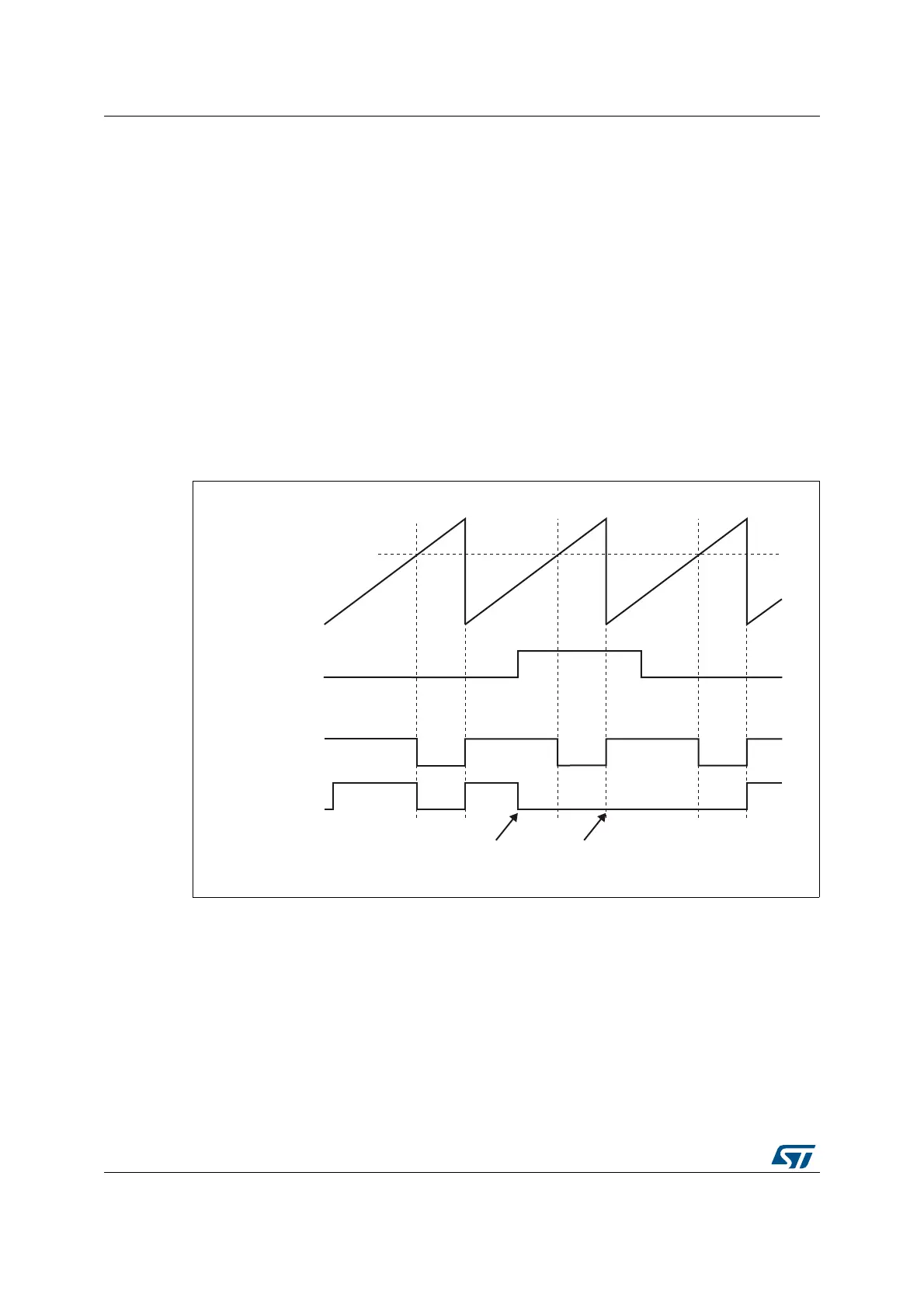
Figure 237 shows the behavior of the OCxREF signal when the ETRF Input becomes High,
for both values of the enable bit OCxCE. In this example, the timer TIMx is programmed in
PWM mode.
Figure 237. Clearing TIMx OCxREF
Note: In case of a PWM with a 100% duty cycle (if CCRx>ARR), then OCxREF is enabled again at
the next counter overflow.
069
&&5[
&RXQWHU&17
(75)
2&[5()
2&[&( µ
2&[5()
2&[&( µ
2&[5()B&/5
EHFRPHVKLJK
2&[5()B&/5
VWLOOKLJK