Advanced-control timers (TIM1/TIM8) RM0351
808/1693 DocID024597 Rev 3
Write CC2P=1 and CC2NP=0 in TIMx_CCER register to validate the polarity (and
detect low level only).
• Configure the timer in trigger mode by writing SMS=110 in TIMx_SMCR register. Select
TI2 as the input source by writing TS=110 in TIMx_SMCR register.
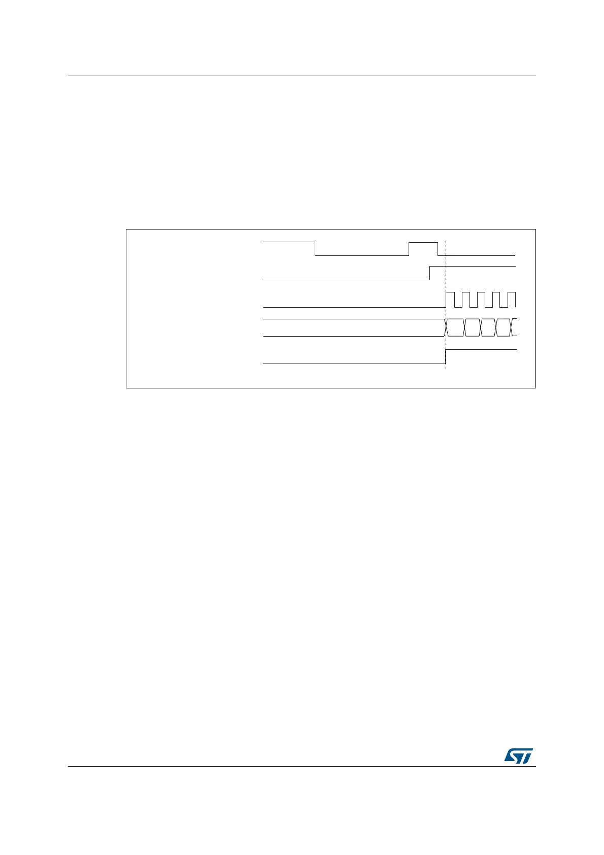
When a rising edge occurs on TI2, the counter starts counting on the internal clock and the
TIF flag is set.
The delay between the rising edge on TI2 and the actual start of the counter is due to the
resynchronization circuit on TI2 input.
Figure 247. Control circuit in trigger mode
Slave mode: Combined reset + trigger mode
In this case, a rising edge of the selected trigger input (TRGI) reinitializes the counter,
generates an update of the registers, and starts the counter.
This mode is used for one-pulse mode.
Slave mode: external clock mode 2 + trigger mode
The external clock mode 2 can be used in addition to another slave mode (except external
clock mode 1 and encoder mode). In this case, the ETR signal is used as external clock
input, and another input can be selected as trigger input (in reset mode, gated mode or
trigger mode). It is recommended not to select ETR as TRGI through the TS bits of
TIMx_SMCR register.
In the following example, the upcounter is incremented at each rising edge of the ETR
signal as soon as a rising edge of TI1 occurs:
069
7,
FQWBHQ
&RXQWHUFORFN FNBFQW FNBSVF
&RXQWHUUHJLVWHU
7,)