General-purpose timers (TIM15/16/17) RM0351
994/1693 DocID024597 Rev 3
28.6.6 TIM16&TIM17 capture/compare mode register 1 (TIMx_CCMR1)
Address offset: 0x18
Reset value: 0x0000 0000
The channels can be used in input (capture mode) or in output (compare mode). The
direction of a channel is defined by configuring the corresponding CCxS bits. All the other
bits of this register have a different function in input and in output mode. For a given bit,
OCxx describes its function when the channel is configured in output, ICxx describes its
function when the channel is configured in input. So you must take care that the same bit
can have a different meaning for the input stage and for the output stage.
Output compare mode:
Bit 0 UG: Update generation
This bit can be set by software, it is automatically cleared by hardware.
0: No action.
1: Reinitialize the counter and generates an update of the registers. Note that the prescaler
counter is cleared too (anyway the prescaler ratio is not affected).
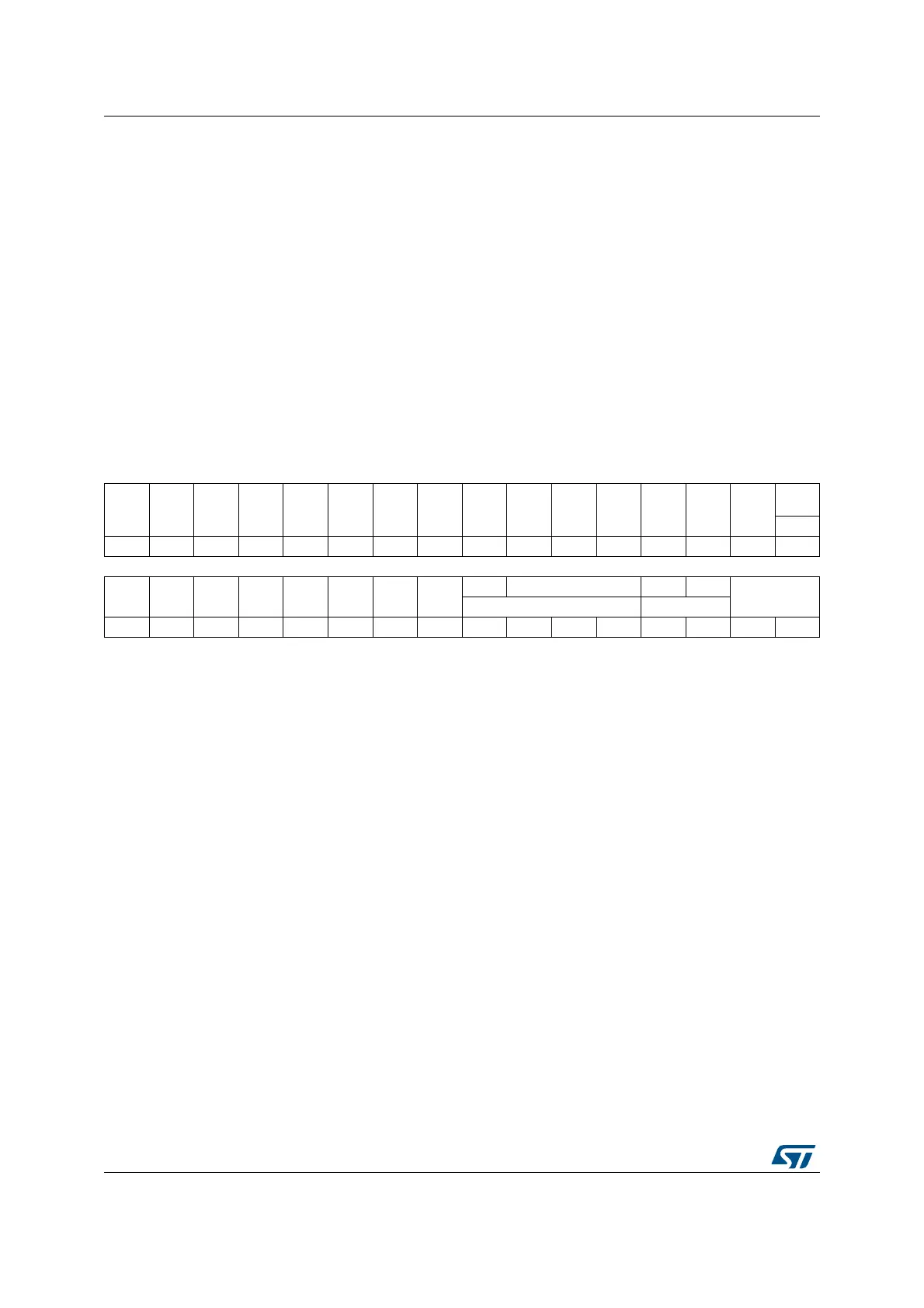
31 30 29 28 27 26 25 24 23 22 21 20 19 18 17 16
Res Res Res Res Res Res Res Res Res Res Res Res Res Res Res
OC1M
[3]
Res
rw
1514131211109876543210
Res Res Res Res Res Res Res Res
Res OC1M[2:0] OC1PE OC1FE
CC1S[1:0]
IC1F[3:0] IC1PSC[1:0]
rw rw rw rw rw rw rw rw
Bits 31:17 Reserved, always read as 0
Bit 16 OC1M[3]: Output Compare 1 mode (bit 3)
Bits 15:7 Reserved

 Loading...


