DocID024597 Rev 3 647/1693
RM0351 Digital filter for sigma delta modulators (DFSDM)
657
21.7.15 DFSDM conversion timer register (DFSDMx_CNVTIMR)
Address offset: 0x100 * (x+1) + 0x038, x = 0...3
Reset value: 0x0000 0000
Bits 31:8 EXMIN[23:0]: Extremes detector minimum value
These bits are set by hardware and indicate the lowest value converted by DFSDM. EXMIN[23:0]
bits are reset to value (0x7FFFFF) by reading of this register.
Bits 7:3 Reserved, must be kept at reset value.
Bits 2:0 EXMINCH[2:0]: Extremes detector minimum data channel
These bits contain information about the channel on which the data is stored into EXMIN[23:0]. Bits
are cleared by reading of this register.
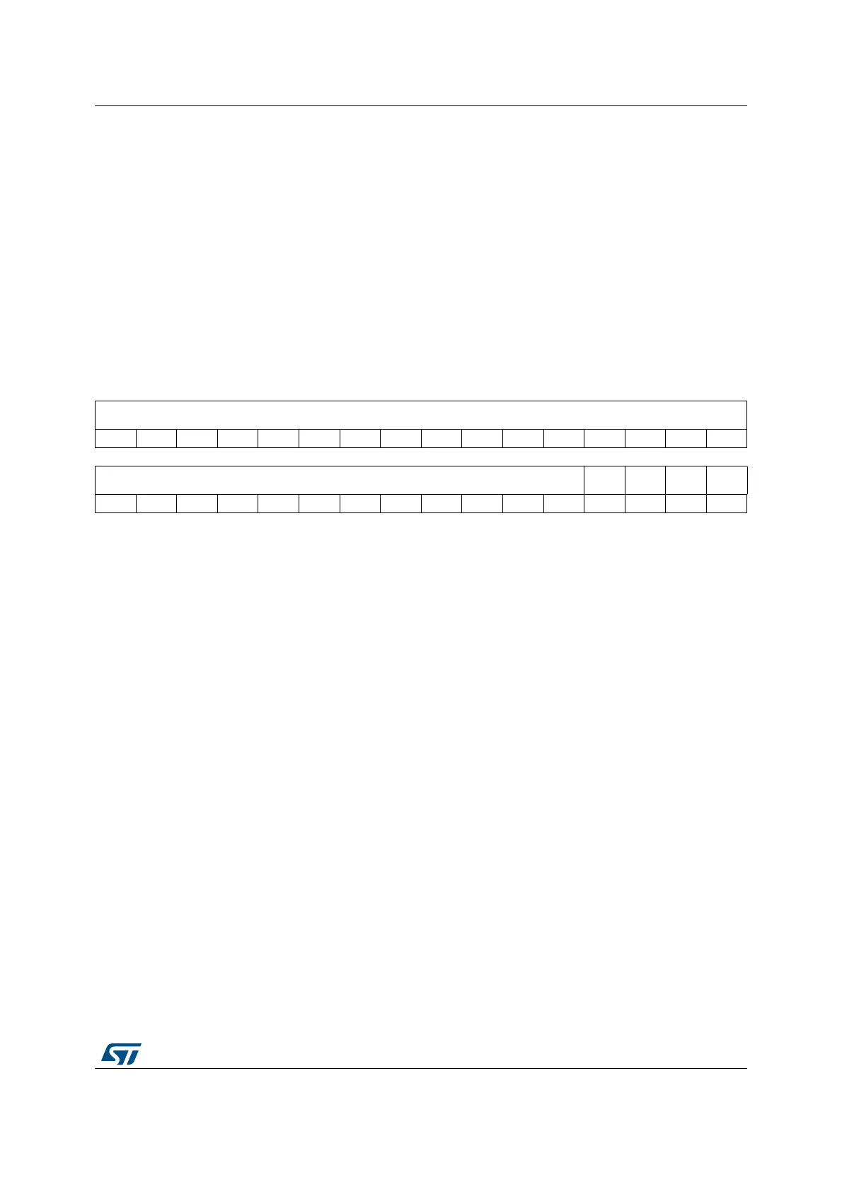
31 30 29 28 27 26 25 24 23 22 21 20 19 18 17 16
CNVCNT[27:12]
rrrrrrrrrrrrrrrr
1514131211109876543210
CNVCNT[11:0] Res. Res. Res. Res.
rrrrrrrrrrrr
Bits 31:4 CNVCNT[27:0]: 28-bit timer counting conversion time t = CNVCNT[27:0] / f
DFSDMCLK
The timer has an input clock from DFSDM clock (system clock f
DFSDMCLK
). Conversion time
measurement is started on each conversion start and stopped when conversion finishes (interval
between first and last serial sample). Only in case of filter bypass (FOSR[9:0] = 0) is the conversion
time measurement stopped and CNVCNT[27:0] = 0. The counted time is:
if FAST=0 (or first conversion in continuous mode if FAST=1):
t = [F
OSR
* (I
OSR
-1 + F
ORD
) + F
ORD
] / f
DFSDM_CKIN
..... for Sinc
x
filters
t = [F
OSR
* (I
OSR
-1 + 4) + 2] / f
DFSDM_CKIN
..... for FastSinc filter
if FAST=1 in continuous mode (except first conversion):
t = [F
OSR
* I
OSR
] / f
DFSDM_CKIN
in case if F
OSR
= FOSR[9:0]+1 = 1 (filter bypassed, active only integrator):
CNVCNT = 0 (counting is stopped, conversion time: t = I
OSR
/ f
DFSDM_CKIN
)
where: f
DFSDM_CKIN
is the channel input clock frequency (on given channel DFSDM_CKINy pin) or
input data rate in case of parallel data input (from CPU/DMA write)
Note: When conversion is interrupted (e.g. by disable/enable selected channel) the timer counts also
this interruption time.
Bits 3:0 Reserved, must be kept at reset value.

 Loading...


