DocID024597 Rev 3 551/1693
RM0351 Digital-to-analog converter (DAC)
573
17.3.11 DAC channel buffer calibration
The transfer function for an N-bit digital-to-analog converter (DAC) is
Where V
out is the analog output, D is the digital input, G is the gain, Vref is the nominal full-
scale voltage, and V
os is the offset voltage.For an ideal DAC channel, G = 1 and Vos = 0.
Due to output buffer characteristics, the voltage offset may differ from part-to-part and
introduce an absolute offset error on the analog output. To compensate the V
os, a calibration
is required by a trimming technique.
The calibration is only valid when the DAC channelx is operating with buffer enabled
(MODEx[2:0] = 000b or 001b or 100b or 101b). if applied in other modes when the buffer is
off, it has no effect. During the calibration:
• The buffer output will be disconnected from the pin internal/external connections and
put in tristate mode (HiZ),
• The buffer will act as a comparator, to sense the middle-code value 0x800 and
compare it to VREF+/2 signal thru an internal bridge, then toggle its output signal to 0
or 1 depending on the comparison result (CAL_FLAGx bit)
Two calibration techniques are provided:
• Factory trimming (always enabled)
The DAC buffer offset is factory trimmed. The default value of OTRIMx[4:0] bits in
DAC_CCR register is the factory trimming value and it is loaded once DAC digital interface
is reset.
• User trimming
The user trimming can be done when the operating conditions differs from nominal factory
trimming conditions and in particular when VDD/VDDA voltage, temperature, VREF+ values
change and can be done at any point during application by software.
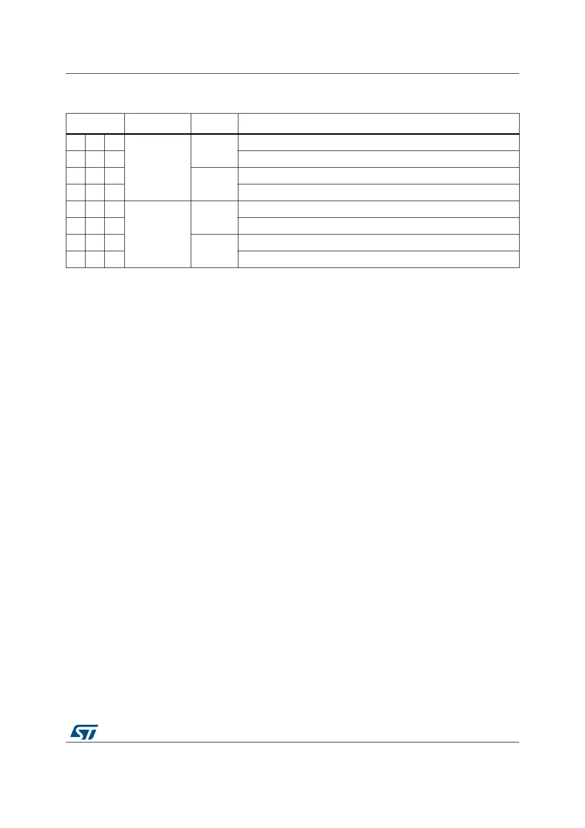
Table 104. Channel output modes summary
MODEx[2:0] Mode Buffer Output connections
000
Normal mode
Enabled
Connected to external pin
0 0 1 Connected to external pin and to on chip-peripherals (ex, comparators)
010
Disabled
Connected to external pin
0 1 1 Connected to on chip peripherals (ex, comparators)
100
Sample & hold
mode
Enabled
Connected to external pin
1 0 1 Connected to external pin and to on chip peripherals (ex, comparators)
110
Disabled
Connected to external pin and to on chip peripherals (ex, comparators)
1 1 1 Connected to on chip peripherals (ex, comparators)
V
out
D2
N1–
⁄()GV
ref
××()V
OS
+=

 Loading...


