Low-power timer (LPTIM) RM0351
1026/1693 DocID024597 Rev 3
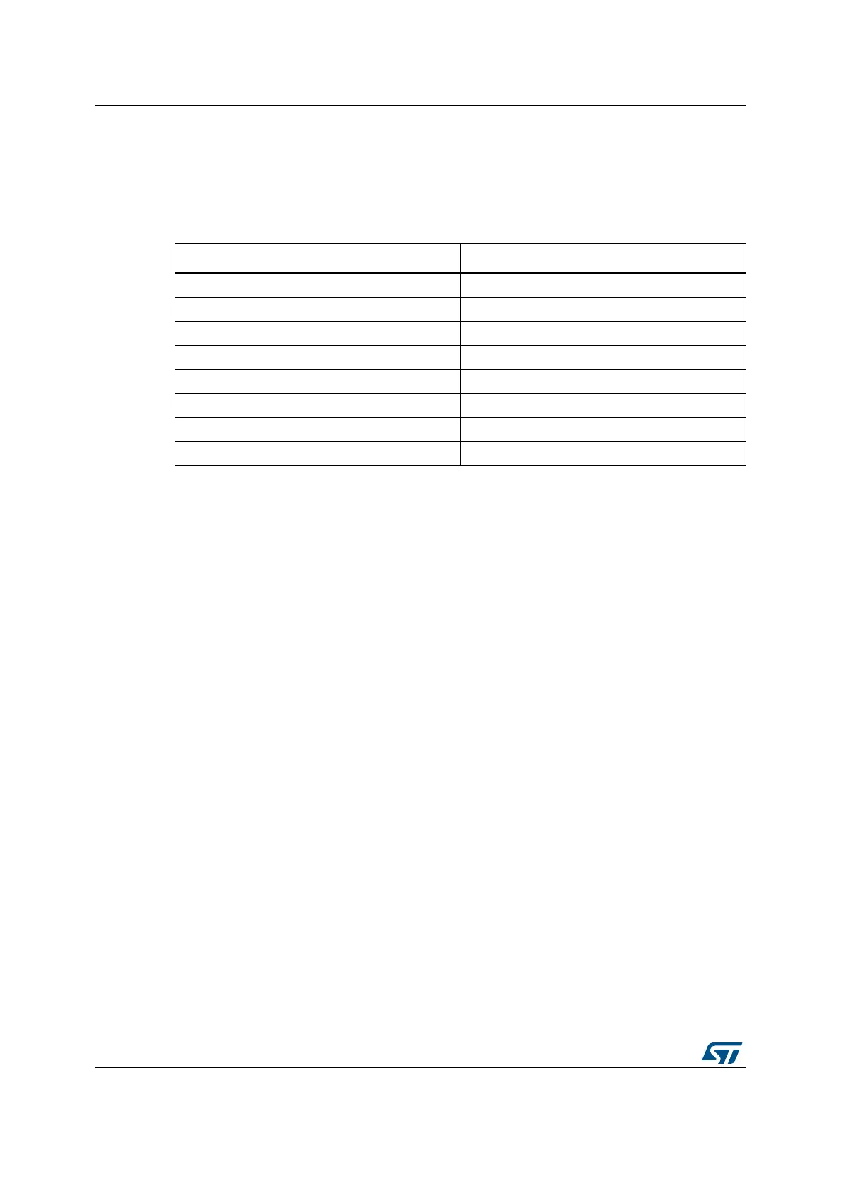
30.4.4 Prescaler
The LPTIM 16-bit counter is preceded by a configurable power-of-2 prescaler. The prescaler
division ratio is controlled by the PRESC[2:0] 3-bit field. The table below lists all the possible
division ratios:
30.4.5 Trigger multiplexer
The LPTIM counter may be started either by software or after the detection of an active
edge on one of the 8 trigger inputs.
TRIGEN[1:0] is used to determine the LPTIM trigger source:
• When TRIGEN[1:0] equals ‘00’, The LPTIM counter is started as soon as one of the
CNTSTRT or the SNGSTRT bits is set by software.
• The three remaining possible values for the TRIGEN[1:0] are used to configure the
active edge used by the trigger inputs. The LPTIM counter starts as soon as an active
edge is detected.
When TRIGEN[1:0] is different than ‘00’, TRIGSEL[2:0] is used to select which of the 8
trigger inputs is used to start the counter.
The external triggers are considered asynchronous signals for the LPTIM. So after a trigger
detection, a two-counter-clock period latency is needed before the timer starts running due
to the synchronization.
If a new trigger event occurs when the timer is already started it will be ignored (unless
timeout function is enabled).
Note: The timer must be enabled before setting the SNGSTRT/CNTSTRT bits. Any write on these
bits when the timer is disabled will be discarded by hardware.
Table 163. Prescaler division ratios
programming dividing factor
000 /1
001 /2
010 /4
011 /8
100 /16
101 /32
110 /64
111 /128

 Loading...


