Quad-SPI interface (QUADSPI) RM0351
414/1693 DocID024597 Rev 3
15.5 QUADSPI registers
15.5.1 QUADSPI control register (QUADSPI_CR)
Address offset: 0x0000
Reset value: 0x0000 0000
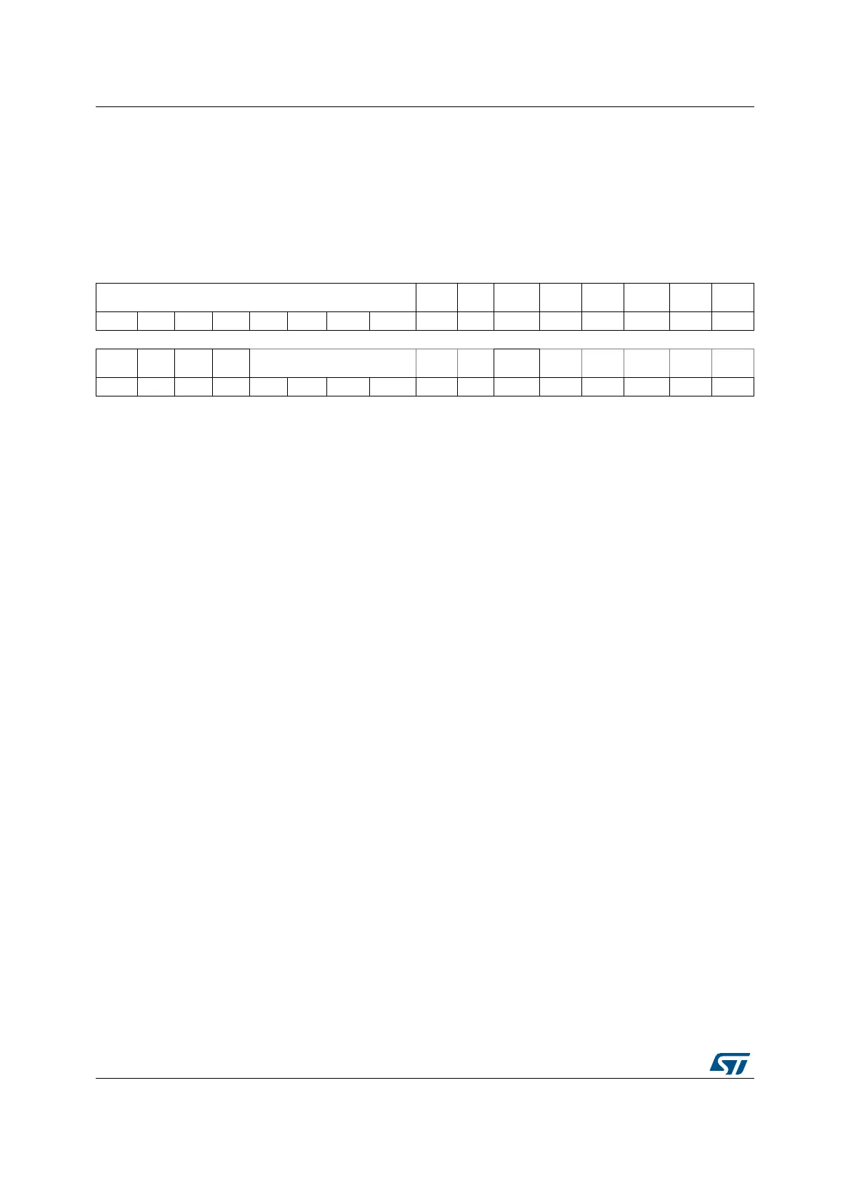
31 30 29 28 27 26 25 24 23 22 21 20 19 18 17 16
PRESCALER PMM APMS Res. TOIE SMIE FTIE TCIE TEIE
rw rw rw rw rw rw rw rw rw rw rw rw rw rw rw
15 14 13 12 11 10 9 8 7 6 5 4 3 2 1 0
Res. Res. Res. Res. FTHRES Res. Res. Res. SSHIFT TCEN DMAEN ABORT EN
rw rw rw rw rw rw w1s rw w1s
Bits 31: 24 PRESCALER[7:0]: Clock prescaler
This field defines the scaler factor for generating CLK based on the AHB clock
(value+1).
0: F
CLK
= F
AHB
, AHB clock used directly as QUADSPI CLK (prescaler bypassed)
1: F
CLK
= F
AHB
/2
2: F
CLK
= F
AHB
/3
...
255: F
CLK
= F
AHB
/256
For odd clock division factors, CLK’s duty cycle is not 50%. The clock signal remains
high one cycle longer than it stays low.
This field can be modified only when BUSY = 0.
Bit 23 PMM: Polling match mode
This bit indicates which method should be used for determining a “match” during
automatic polling mode.
0: AND match mode. SMF is set if all the unmasked bits received from the Flash
memory match the corresponding bits in the match register.
1: OR match mode. SMF is set if any one of the unmasked bits received from the Flash
memory matches its corresponding bit in the match register.
This bit can be modified only when BUSY = 0.
Bit 22 APMS: Automatic poll mode stop
This bit determines if automatic polling is stopped after a match.
0: Automatic polling mode is stopped only by abort or by disabling the QUADSPI.
1: Automatic polling mode stops as soon as there is a match.
This bit can be modified only when BUSY = 0.
Bit 21 Reserved, must be kept at reset value.
Bit 20 TOIE: TimeOut interrupt enable
This bit enables the TimeOut interrupt.
0: Interrupt disable
1: Interrupt enabled
Bit 19 SMIE: Status match interrupt enable
This bit enables the status match interrupt.
0: Interrupt disable
1: Interrupt enabled

 Loading...


