DocID024597 Rev 3 1209/1693
RM0351 Universal synchronous asynchronous receiver transmitter (USART)
1282
desired CGT (Character Guard Time, as defined by the 7816-3 specification) minus 12
(the duration of one character).
• The assertion of the TC flag can be delayed by programming the Guard Time register.
In normal operation, TC is asserted when the transmit shift register is empty and no
further transmit requests are outstanding. In Smartcard mode an empty transmit shift
register triggers the Guard Time counter to count up to the programmed value in the
Guard Time register. TC is forced low during this time. When the Guard Time counter
reaches the programmed value TC is asserted high.
• The de-assertion of TC flag is unaffected by Smartcard mode.
• If a framing error is detected on the transmitter end (due to a NACK from the receiver),
the NACK is not detected as a start bit by the receive block of the transmitter.
According to the ISO protocol, the duration of the received NACK can be 1 or 2 baud
clock periods.
• On the receiver side, if a parity error is detected and a NACK is transmitted the receiver
does not detect the NACK as a start bit.
Note: A break character is not significant in Smartcard mode. A 0x00 data with a framing error is
treated as data and not as a break.
No Idle frame is transmitted when toggling the TE bit. The Idle frame (as defined for the
other configurations) is not defined by the ISO protocol.
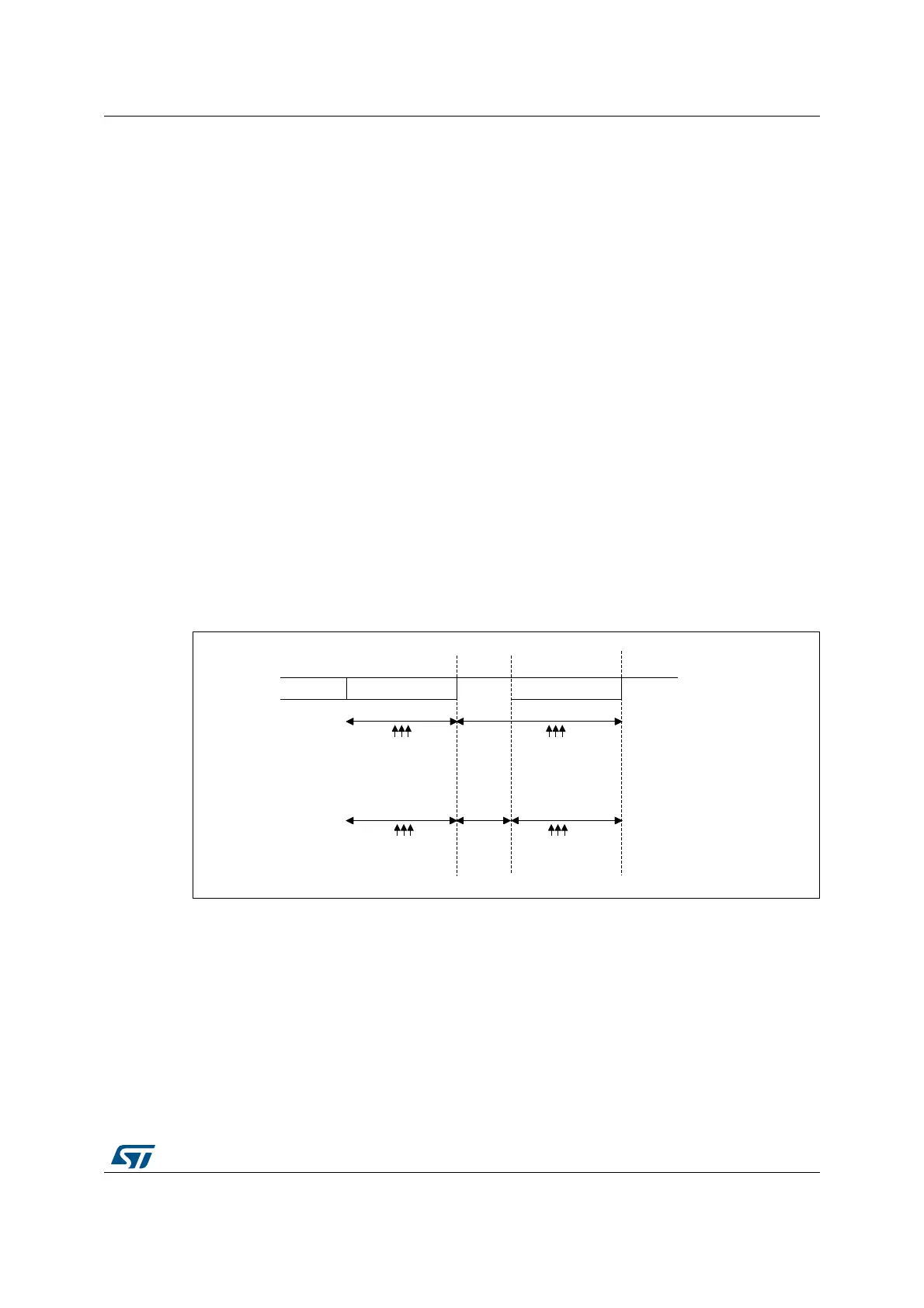
Figure 399 details how the NACK signal is sampled by the USART. In this example the
USART is transmitting data and is configured with 1.5 stop bits. The receiver part of the
USART is enabled in order to check the integrity of the data and the NACK signal.
Figure 399. Parity error detection using the 1.5 stop bits
The USART can provide a clock to the smartcard through the CK output. In Smartcard
mode, CK is not associated to the communication but is simply derived from the internal
peripheral input clock through a 5-bit prescaler. The division ratio is configured in the
prescaler register USARTx_. CK frequency can be programmed from f
CK
/2 to f
CK
/62, where
f
CK
is the peripheral input clock.
06Y9
%LW
3DULW\ELW
6WRSELW
ELWWLPH ELWWLPH
ELWWLPH
6DPSOLQJDW
WKWKWK
6DPSOLQJDW
WKWKWK
6DPSOLQJDW
WKWKWK
6DPSOLQJDW
WKWKWK

 Loading...


