DocID024597 Rev 3 789/1693
RM0351 Advanced-control timers (TIM1/TIM8)
856
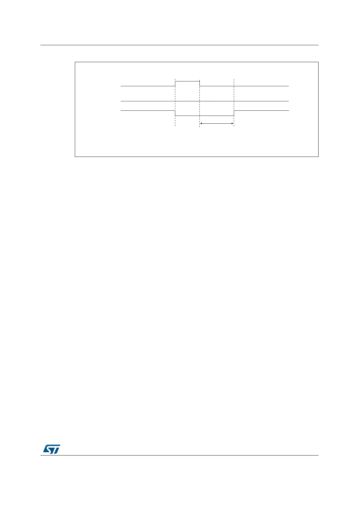
Figure 231. Dead-time waveforms with delay greater than the positive pulse
The dead-time delay is the same for each of the channels and is programmable with the
DTG bits in the TIMx_BDTR register. Refer to Section 26.4.18: TIM1/TIM8 break and dead-
time register (TIMx_BDTR) on page 836 for delay calculation.
Re-directing OCxREF to OCx or OCxN
In output mode (forced, output compare or PWM), OCxREF can be re-directed to the OCx
output or to OCxN output by configuring the CCxE and CCxNE bits in the TIMx_CCER
register.
This allows you to send a specific waveform (such as PWM or static active level) on one
output while the complementary remains at its inactive level. Other alternative possibilities
are to have both outputs at inactive level or both outputs active and complementary with
dead-time.
Note: When only OCxN is enabled (CCxE=0, CCxNE=1), it is not complemented and becomes
active as soon as OCxREF is high. For example, if CCxNP=0 then OCxN=OCxRef. On the
other hand, when both OCx and OCxN are enabled (CCxE=CCxNE=1) OCx becomes
active when OCxREF is high whereas OCxN is complemented and becomes active when
OCxREF is low.
26.3.16 Using the break function
The purpose of the break function is to protect power switches driven by PWM signals
generated with the TIM1 and TIM8 timers. The two break inputs are usually connected to
fault outputs of power stages and 3-phase inverters. When activated, the break circuitry
shuts down the PWM outputs and forces them to a predefined safe state. A number of
internal MCU events can also be selected to trigger an output shut-down.
The break features two channels. A break channel which gathers both system-level fault
(clock failure, parity error,...) and application fault (from input pins and built-in comparator),
and can force the outputs to a predefined level (either active or inactive) after a deadtime
duration. A break2 channel which only includes application faults and is able to force the
outputs to an inactive state.
069
GHOD\
2&[5()
2&[
2&[1

 Loading...


