DocID024597 Rev 3 1261/1693
RM0351 Low-power universal asynchronous receiver transmitter (LPUART)
1282
1. Write the LPUART_TDR register address in the DMA control register to configure it as
the destination of the transfer. The data is moved to this address from memory after
each TXE event.
2. Write the memory address in the DMA control register to configure it as the source of
the transfer. The data is loaded into the LPUART_TDR register from this memory area
after each TXE event.
3. Configure the total number of bytes to be transferred to the DMA control register.
4. Configure the channel priority in the DMA register
5. Configure DMA interrupt generation after half/ full transfer as required by the
application.
6. Clear the TC flag in the LPUART_ISR register by setting the TCCF bit in the
LPUART_ICR register.
7. Activate the channel in the DMA register.
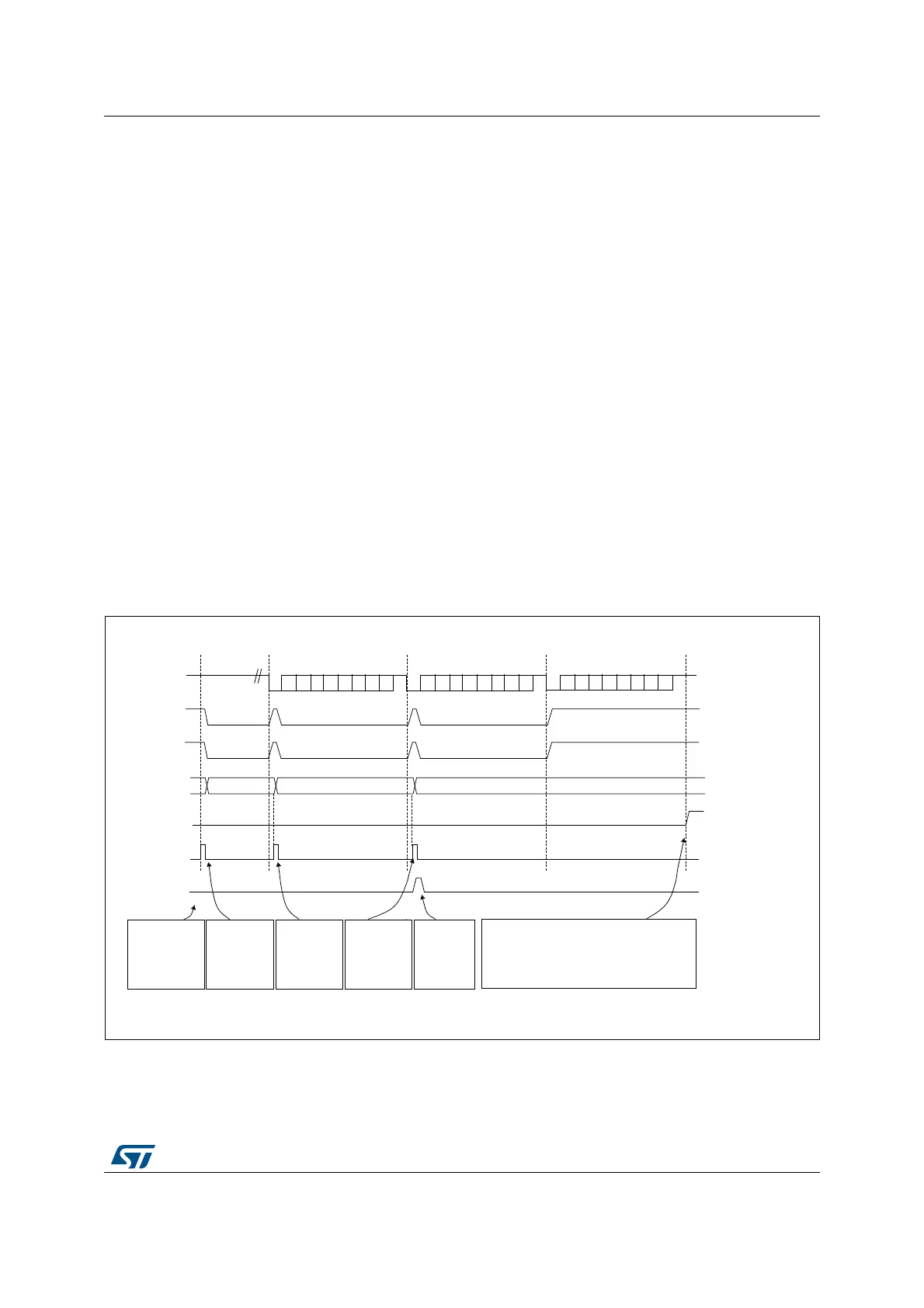
When the number of data transfers programmed in the DMA Controller is reached, the DMA
controller generates an interrupt on the DMA channel interrupt vector.
In transmission mode, once the DMA has written all the data to be transmitted (the TCIF flag
is set in the DMA_ISR register), the TC flag can be monitored to make sure that the
LPUART communication is complete. This is required to avoid corrupting the last
transmission before disabling the LPUART or entering Stop mode. Software must wait until
TC=1. The TC flag remains cleared during all data transfers and it is set by hardware at the
end of transmission of the last frame.
Figure 414. Transmission using DMA
) ))
06Y9
6RIWZDUH
FRQILJXUHV
'0$WRVHQG
GDWDEORFNV
DQGHQDEOHV
/38$57
7KH'0$
WUDQVIHULV
FRPSOHWH
7&,) LQ
'0$B,65
'0$ZULWHV)
LQWR
/38$57B7'5
'0$ZULWHV)
LQWR
/38$57B7'5
6RIWZDUHZDLWVXQWLO7&
6HWE\KDUGZDUH
&OHDUHGE\VRIWZDUH
6HWE\KDUGZDUH
7;OLQH
7;(IODJ
/38$57B7'5
'0$UHTXHVW
'0$ZULWHV
/38$57B7'5
'0$7&,)IODJWUDQVIHUFRPSOHWH
7&IODJ
)UDPH
)UDPH
)UDPH
,GOHSUHDPEOH
6HWE\KDUGZDUHFOHDUHG
E\'0$UHDG
6HWE\KDUGZDUHFOHDUHGE\
'0$UHDG
6HWE\KDUGZDUH
,JQRUHGE\WKH'0$EHFDXVHWKHWUDQVIHU
LVFRPSOHWH
D
'0$ZULWHV)
LQWR
/38$57B7'5

 Loading...


