Serial audio interface (SAI) RM0351
1326/1693 DocID024597 Rev 3
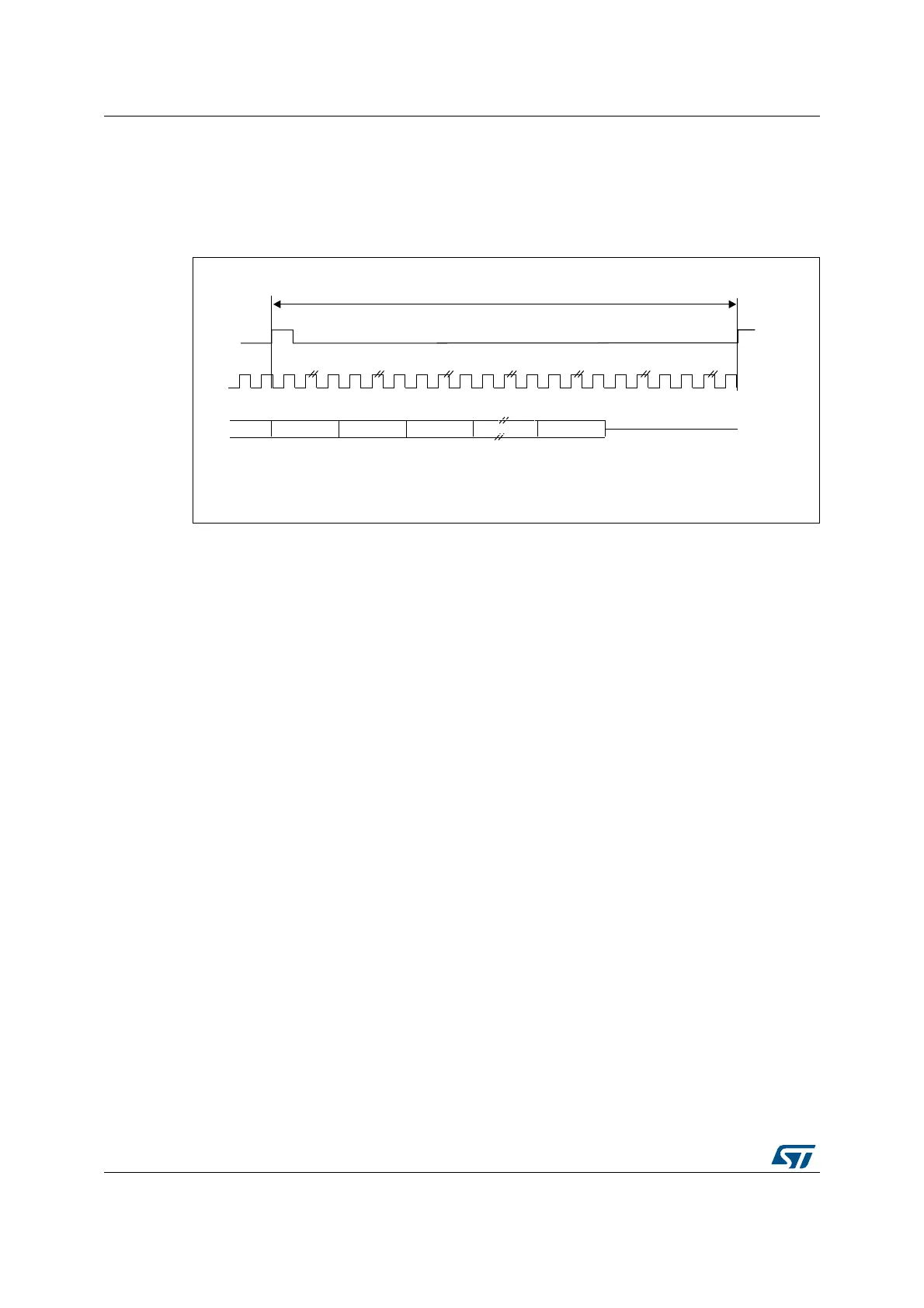
• if TRIS = 0 in the SAI_xCR2 register, the remaining bit after the last slot will be forced to
0 until the end of frame in case of transmitter,
• if TRIS = 1, the line will be released to HI-Z during the transfer of these remaining bits.
In reception mode, these bits are discarded.
Figure 439. FS role is start of frame (FSDEF = 0)
The FS signal is not used when the audio block in transmitter mode is configured to get the
SPDIF output on the SD line. The corresponding FS I/O will be released and left free for
other purposes.
39.3.6 Slot configuration
The slot is the basic element in the audio frame. The number of slots in the audio frame is
equal to NBSLOT[3:0] + 1.
The maximum number of slots per audio frame is fixed at 16.
For AC’97 protocol or SPDIF (when bit PRTCFG[1:0] = 10 or PRTCFG[1:0] = 01), the
number of slots is automatically set to target the protocol specification, and the value of
NBSLOT[3:0] is ignored.
Each slot can be defined as a valid slot, or not, by setting SLOTEN[15:0] bits of the
SAI_xSLOTR register.
When a invalid slot is transferred, the SD data line is either forced to 0 or released to HI-z
depending on TRIS bit configuration (refer to Section : Output data line management on an
inactive slot) in transmitter mode. In receiver mode, the received value from the end of this
slot is ignored. Consequently, there will be no FIFO access and so no request to read or
write the FIFO linked to this inactive slot status.
The slot size is also configurable as shown in Figure 440. The size of the slots is selected by
setting SLOTSZ[1:0] bits in the SAI_xSLOTR register. The size is applied identically for
each slot in an audio frame.
$XGLRIUDPH
'DWD DIWHUVORWQLI75,6
6'RXWSXWUHOHDVHG+,=DIWHUVORWQLI75,6
069
VFN
VORW
6ORW 6ORW
6ORW 6ORWQ

 Loading...


