DocID024597 Rev 3 803/1693
RM0351 Advanced-control timers (TIM1/TIM8)
856
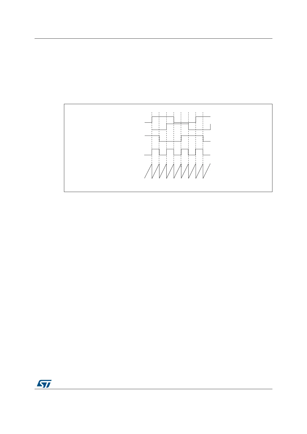
26.3.24 Timer input XOR function
The TI1S bit in the TIMx_CR2 register, allows the input filter of channel 1 to be connected to
the output of an XOR gate, combining the two input pins TIMx_CH1 and TIMx_CH2.
The XOR output can be used with all the timer input functions such as trigger or input
capture. It is convenient to measure the interval between edges on two input signals, as per
Figure 243 below.
Figure 243. Measuring time interval between edges on 3 signals
26.3.25 Interfacing with Hall sensors
This is done using the advanced-control timers (TIM1 or TIM8) to generate PWM signals to
drive the motor and another timer TIMx (TIM2, TIM3, TIM4) referred to as “interfacing timer”
in Figure 244. The “interfacing timer” captures the 3 timer input pins (CC1, CC2, CC3)
connected through a XOR to the TI1 input channel (selected by setting the TI1S bit in the
TIMx_CR2 register).
The slave mode controller is configured in reset mode; the slave input is TI1F_ED. Thus,
each time one of the 3 inputs toggles, the counter restarts counting from 0. This creates a
time base triggered by any change on the Hall inputs.
On the “interfacing timer”, capture/compare channel 1 is configured in capture mode,
capture signal is TRC (See Figure 217: Capture/compare channel (example: channel 1
input stage) on page 775). The captured value, which corresponds to the time elapsed
between 2 changes on the inputs, gives information about motor speed.
The “interfacing timer” can be used in output mode to generate a pulse which changes the
configuration of the channels of the advanced-control timer (TIM1 or TIM8) (by triggering a
COM event). The TIM1 timer is used to generate PWM signals to drive the motor. To do this,
the interfacing timer channel must be programmed so that a positive pulse is generated
after a programmed delay (in output compare or PWM mode). This pulse is sent to the
advanced-control timer (TIM1 or TIM8) through the TRGO output.
069
7,
7,
;25
&RXQWHU
7,
7,0[

 Loading...


