DocID024597 Rev 3 951/1693
RM0351 General-purpose timers (TIM15/16/17)
1009
by the two TIMx_CCRx registers. The resulting signals, OCxREFC, are made of an OR or
AND logical combination of two reference PWMs:
• OC1REFC (or OC2REFC) is controlled by the TIMx_CCR1 and TIMx_CCR2 registers
Combined PWM mode can be selected independently on two channels (one OCx output per
pair of CCR registers) by writing ‘1100’ (Combined PWM mode 1) or ‘1101’ (Combined PWM
mode 2) in the OCxM bits in the TIMx_CCMRx register.
When a given channel is used as a combined PWM channel, its complementary channel
must be configured in the opposite PWM mode (for instance, one in Combined PWM mode
1 and the other in Combined PWM mode 2).
Note: The OCxM[3:0] bit field is split into two parts for compatibility reasons, the most significant
bit is not contiguous with the 3 least significant ones.
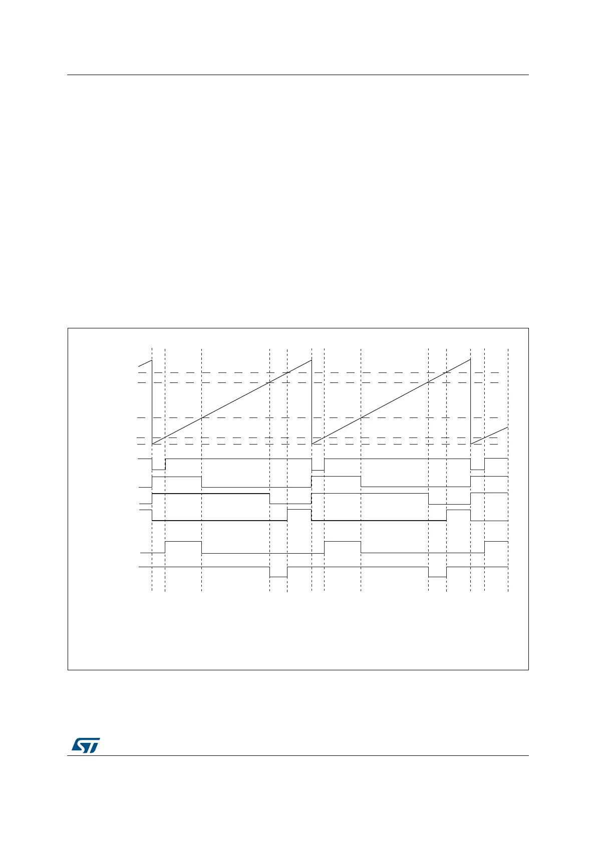
Figure 319 represents an example of signals that can be generated using Asymmetric PWM
mode, obtained with the following configuration:
• Channel 1 is configured in Combined PWM mode 2,
• Channel 2 is configured in PWM mode 1,
Figure 319. Combined PWM mode on channel 1 and 2
069
2&5()
2&5()
2&5()
2&5()
2&5()&
2&5()&
2&5()& 2&5()$1'2&5()
2&5()&¶ 2&5()¶252&5()
2&
2&
2&
2&

 Loading...


