Universal synchronous asynchronous receiver transmitter (USART) RM0351
1200/1693 DocID024597 Rev 3
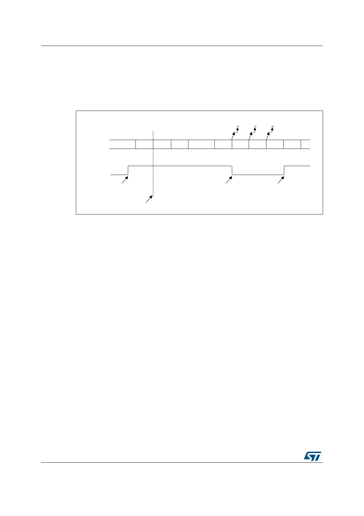
The USART exits from mute mode when an address character is received which matches
the programmed address. Then the RWU bit is cleared and subsequent bytes are received
normally. The RXNE bit is set for the address character since the RWU bit has been
cleared.
An example of mute mode behavior using address mark detection is given in Figure 391.
Figure 391. Mute mode using address mark detection
36.5.8 Modbus communication using USART
The USART offers basic support for the implementation of Modbus/RTU and Modbus/ASCII
protocols. Modbus/RTU is a half duplex, block transfer protocol. The control part of the
protocol (address recognition, block integrity control and command interpretation) must be
implemented in software.
The USART offers basic support for the end of the block detection, without software
overhead or other resources.
Modbus/RTU
In this mode, the end of one block is recognized by a “silence” (idle line) for more than 2
character times. This function is implemented through the programmable timeout function.
The timeout function and interrupt must be activated, through the RTOEN bit in the
USARTx_CR2 register and the RTOIE in the USARTx_CR1 register. The value
corresponding to a timeout of 2 character times (for example 22 x bit duration) must be
programmed in the RTO register. when the receive line is idle for this duration, after the last
stop bit is received, an interrupt is generated, informing the software that the current block
reception is completed.
Modbus/ASCII
In this mode, the end of a block is recognized by a specific (CR/LF) character sequence.
The USART manages this mechanism using the character match function.
By programming the LF ASCII code in the ADD[7:0] field and by activating the character
match interrupt (CMIE=1), the software is informed when a LF has been received and can
check the CR/LF in the DMA buffer.
06Y9
,'/( $GGU 'DWD 'DWD ,'/( $GGU 'DWD 'DWD $GGU 'DWD
,QWKLVH[DPSOHWKHFXUUHQWDGGUHVVRIWKHUHFHLYHULV
SURJUDPPHGLQWKH86$57B&5UHJLVWHU
5;1(
1RQPDWFKLQJDGGUHVV0DWFKLQJDGGUHVV
1RQPDWFKLQJDGGUHVV
0054ZULWWHQWR
5;1(ZDVFOHDUHG
5:8
5;
0XWHPRGH 0XWHPRGH1RUPDOPRGH
5;1( 5;1(

 Loading...


