Advanced-control timers (TIM1/TIM8) RM0351
774/1693 DocID024597 Rev 3
1. As no filter is needed in this example, write ETF[3:0]=0000 in the TIMx_SMCR register.
2. Set the prescaler by writing ETPS[1:0]=01 in the TIMx_SMCR register
3. Select rising edge detection on the ETR pin by writing ETP=0 in the TIMx_SMCR
register
4. Enable external clock mode 2 by writing ECE=1 in the TIMx_SMCR register.
5. Enable the counter by writing CEN=1 in the TIMx_CR1 register.
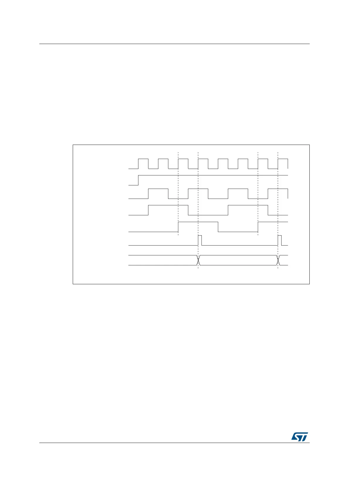
The counter counts once each 2 ETR rising edges.
The delay between the rising edge on ETR and the actual clock of the counter is due to the
resynchronization circuit on the ETRP signal.
Figure 216. Control circuit in external clock mode 2
069
I
&.B,17
&17B(1
(75
(753
(75)
&RXQWHUFORFN
&.B,17 &.B36&
&RXQWHUUHJLVWHU

 Loading...


