DocID024597 Rev 3 769/1693
RM0351 Advanced-control timers (TIM1/TIM8)
856
26.3.4 External trigger input
The timer features an external trigger input ETR. It can be used as:
• external clock (external clock mode 2, see Section 26.3.5)
• trigger for the slave mode (see Section 26.3.26)
• PWM reset input for cycle-by-cycle current regulation (see Section 26.3.7)
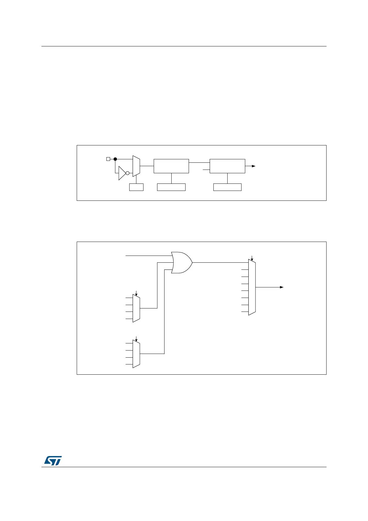
Figure 209 below describes the ETR input conditioning. The input polarity is defined with
with the ETP bit in TIMxSMCR register. The trigger can be prescaled with the divider
programmed by the ETPS[1:0] bitfield and digitally filtered with the ETF[3:0] bitfield.
Figure 209. External trigger input block
The ETR input comes from multiple sources: input pins (default configuration), comparator
outputs and analog watchdogs. The selection is done with the ETRSEL[2:0] bitfield in the
TIMx_OR2 register and the TIMxOR1[1:0] and TIMxOR1[3:2] bitfields.
Figure 210. TIM1 ETR input circuitry
069
7RWKH2XWSXWPRGHFRQWUROOHU
7RWKH&.B36&FLUFXLWU\
7RWKH6ODYHPRGHFRQWUROOHU
(75LQSXW
(75
(73
7,0[B60&5
'LYLGHU
(736>@
7,0[B60&5
)LOWHU
GRZQFRXQWHU
(7)>@
7,0[B60&5
(753
I
'76
069
$'&B$:'
7,0B25>@
$'&B$:'
$'&B$:'
1&
$'&B$:'
$'&B$:'
$'&B$:'
1&
7,0B25>@
(75LQSXWVIURP
$)FRQWUROOHU
7,0B25>@
(75OHJDF\PRGH
&203
&203
1&
1&
1&
1&
1&
(75LQSXW