Low-power timer (LPTIM) RM0351
1038/1693 DocID024597 Rev 3
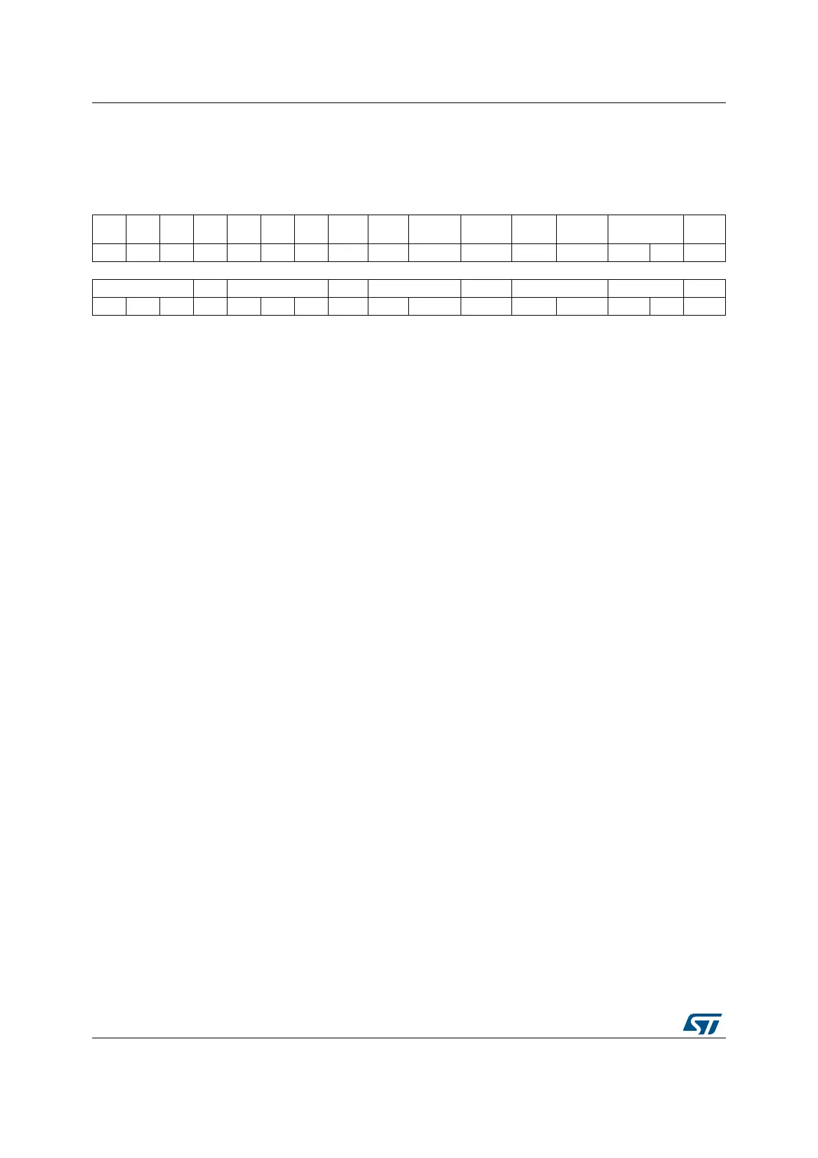
30.7.4 LPTIM configuration register (LPTIMx_CFGR)
Address offset: 0x0C
Reset value: 0x0000 0000
31 30 29 28 27 26 25 24 23 22 21 20 19 18 17 16
Res. Res. Res. Res. Res. Res. Res. ENC
COUNT
MODE
PRELOAD WAVPOL WAVE TIMOUT TRIGEN Res.
rw rw rw rw rw rw rw rw
15 14 13 12 11 10 9 8 7 6 5 4 3 2 1 0
TRIGSEL Res. PRESC Res. TRGFLT Res. CKFLT CKPOL CKSEL
rw rw rw rw rw rw rw rw rw rw rw rw rw
Bits 31:25 Reserved, must be kept at reset value.
Bit 24 ENC: Encoder mode enable
The ENC bit controls the Encoder mode
0: Encoder mode disabled
1: Encoder mode enabled
Bit 23 COUNTMODE: counter mode enabled
The COUNTMODE bit selects which clock source is used by the LPTIM to clock the counter:
0: the counter is incremented following each internal clock pulse
1: the counter is incremented following each valid clock pulse on the LPTIM external Input1
Bit 22 PRELOAD: Registers update mode
The PRELOAD bit controls the LPTIMx_ARR and the LPTIMx_CMP registers update modality
0: Registers are updated after each APB bus write access
1: Registers are updated at the end of the current LPTIM period
Bit 21 WAVPOL: Waveform shape polarity
The WAVEPOL bit controls the output polarity
0: The LPTIM output reflects the compare results between LPTIMx_ARR and LPTIMx_CMP
registers
1: The LPTIM output reflects the inverse of the compare results between LPTIMx_ARR and
LPTIMx_CMP registers
Bit 20 WAVE: Waveform shape
The WAVE bit controls the output shape
0: Deactivate Set-once mode, PWM / One Pulse waveform (depending on OPMODE bit)
1: Activate the Set-once mode
Bit 19 TIMOUT: Timeout enable
The TIMOUT bit controls the Timeout feature
0: a trigger event arriving when the timer is already started will be ignored
1: A trigger event arriving when the timer is already started will reset and restart the counter
Bits18:17 TRIGEN: Trigger enable and polarity
The TRIGEN bits controls whether the LPTIM counter is started by an external trigger or not. If the
external trigger option is selected, three configurations are possible for the trigger active edge:
00: sw trigger (counting start is initiated by software)
01: rising edge is the active edge
10: falling edge is the active edge
11: both edges are active edges
Bit 16 Reserved, must be kept at reset value.

 Loading...


