Inter-integrated circuit (I2C) interface RM0351
1108/1693 DocID024597 Rev 3
The following additional features are also available depending on the product
implementation (see Section 35.3: I2C implementation):
• SMBus specification rev 2.0 compatibility:
– Hardware PEC (Packet Error Checking) generation and verification with ACK
control
– Command and data acknowledge control
– Address resolution protocol (ARP) support
– Host and Device support
– SMBus alert
– Timeouts and idle condition detection
• PMBus rev 1.1 standard compatibility
• Independent clock: a choice of independent clock sources allowing the I2C
communication speed to be independent from the PCLK reprogramming
• Wakeup from Stop mode on address match.
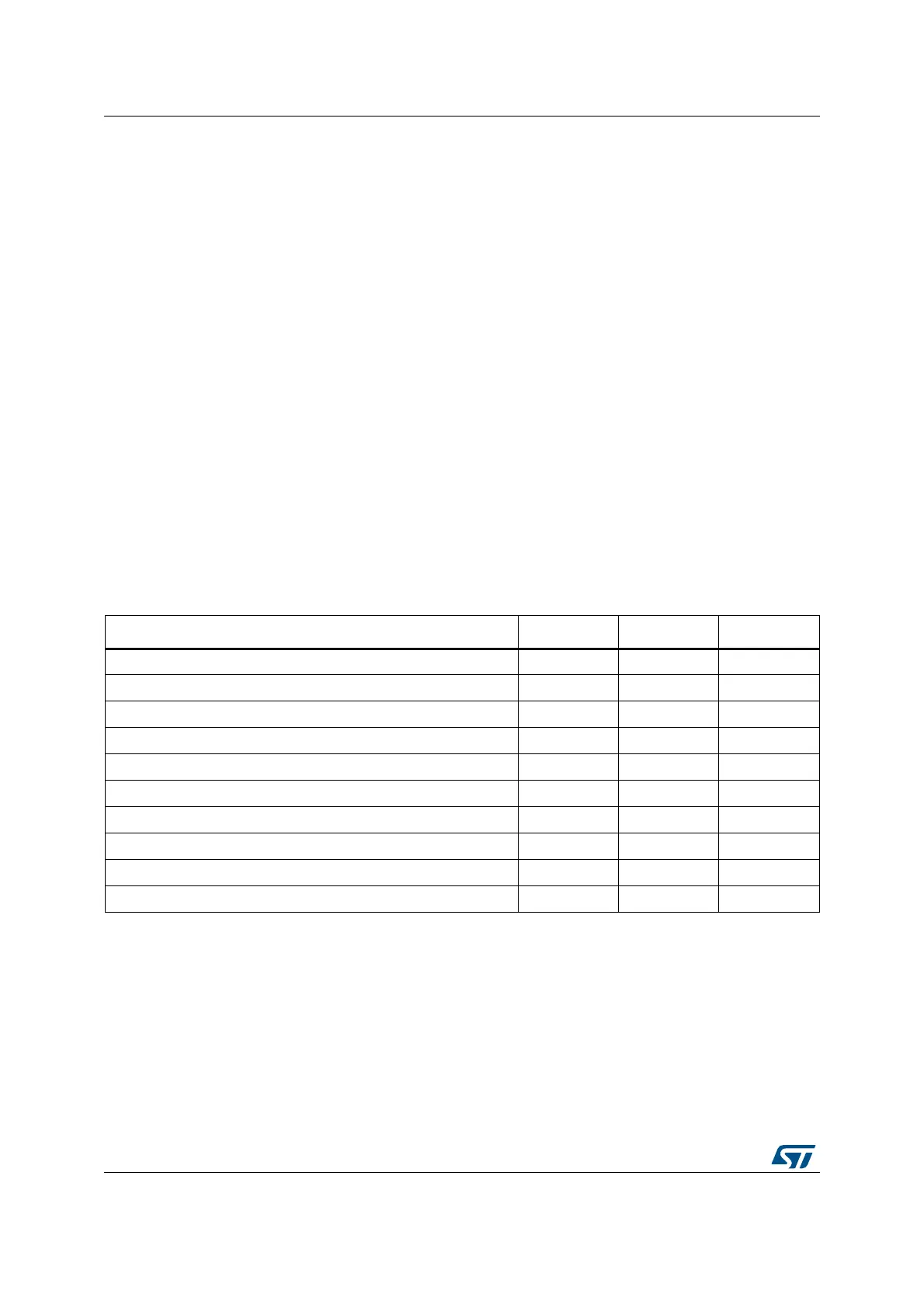
35.3 I2C implementation
This manual describes the full set of features implemented in I2C peripheral. In the
STM32L4x6 devices I2C1, I2C2 and I2C3 implement the full set of features as shown in the
following table, with the restriction than only I2C3 can wake up from Stop 2 mode.
35.4 I2C functional description
In addition to receiving and transmitting data, this interface converts it from serial to parallel
format and vice versa. The interrupts are enabled or disabled by software. The interface is
connected to the I
2
C bus by a data pin (SDA) and by a clock pin (SCL). It can be connected
with a standard (up to 100 kHz), Fast-mode (up to 400 kHz) or Fast-mode Plus (up to
1MHz) I
2
C bus.
Table 175. STM32L4x6 I2C implementation
I2C features
(1)
I2C1 I2C2 I2C3
7-bit addressing mode X X X
10-bit addressing mode X X X
Standard-mode (up to 100 kbit/s) X X X
Fast-mode (up to 400 kbit/s) X X X
Fast-mode Plus with 20mA output drive I/Os (up to 1 Mbit/s) X X X
Independent clock X X X
SMBus X X X
Wakeup from Stop 0 mode X X X
Wakeup from Stop 1 mode X X X
Wakeup from Stop 2 mode - - X
1. X = supported.