Debug support (DBG) RM0351
1672/1693 DocID024597 Rev 3
TPUI TRACE pin assignment
By default, these pins are NOT assigned. They can be assigned by setting the
TRACE_IOEN and TRACE_MODE bits in the Debug MCU configuration register
(DBGMCU_CR). This configuration has to be done by the debugger host.
In addition, the number of pins to assign depends on the trace configuration (asynchronous
or synchronous).
• Asynchronous mode: 1 extra pin is needed
• Synchronous mode: from 2 to 5 extra pins are needed depending on the size of the
data trace port register (1, 2 or 4) :
– TRACECK
– TRACED(0) if port size is configured to 1, 2 or 4
– TRACED(1) if port size is configured to 2 or 4
– TRACED(2) if port size is configured to 4
– TRACED(3) if port size is configured to 4
To assign the TRACE pin, the debugger host must program the bits TRACE_IOEN and
TRACE_MODE[1:0] of the Debug MCU configuration register (DBGMCU_CR). By default
the TRACE pins are not assigned.
This register is mapped on the external PPB and is reset by the PORESET (and not by the
SYSTEM reset). It can be written by the debugger under SYSTEM reset.
Table 277. Synchronous TRACE pin assignment
TPUI pin name
Trace synchronous mode
STM32L4x6 pin
assignment
Type Description
TRACECK O TRACE Clock PE2
TRACED[3:0] O
TRACE Synchronous Data Outputs
Can be 1, 2 or 4.
PE[6:3]
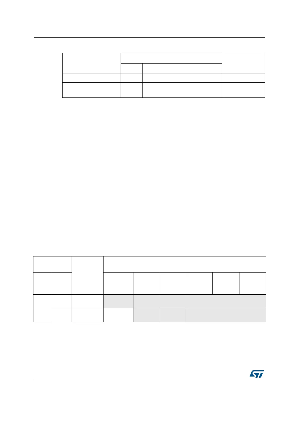
Table 278. Flexible TRACE pin assignment
DBGMCU_CR
register
Pins
assigned for:
TRACE IO pin assigned
TRACE
_IOEN
TRACE
_MODE
[1:0]
PB3 / JTDO/
TRACESWO
PE2 /
TRACECK
PE3 /
TRACED[0]
PE4 /
TRACED[1]
PE5 /
TRACED[2]
PE6 /
TRACED[3]
0XX
No Trace
(default state)
Released
(1)
-
100
Asynchronous
Trace
TRACESWO
- -
Released
(usable as GPIO)

 Loading...


