Digital-to-analog converter (DAC) RM0351
548/1693 DocID024597 Rev 3
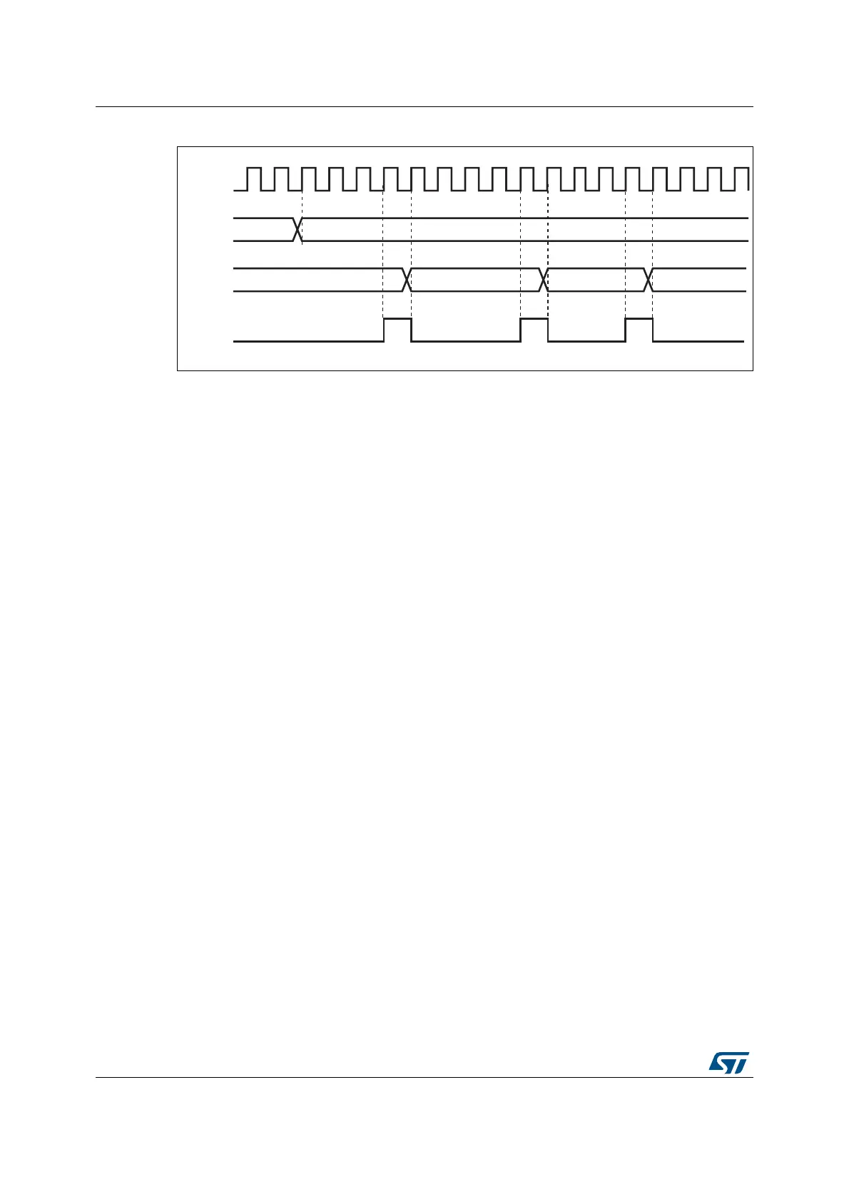
Figure 136. DAC conversion (SW trigger enabled) with triangle wave generation
Note: 1 The DAC trigger must be enabled for noise generation by setting the TENx bit in the
DAC_CR register.
2 The MAMPx[3:0] bits must be configured before enabling the DAC, otherwise they cannot
be changed.
17.3.10 DAC channel modes
Each DAC channel can be configured in normal mode or sample and hold mode. The output
buffer can be enabled to allow a high drive capability. Before enabling output buffer, the
voltage offset needs to be calibrated. This calibration is performed at the factory (loaded
after reset) and can be adjusted by software during application operation.
Normal Mode
In normal mode, there are four combinations, by changing the buffer state and by changing
the DAC_OUTx pin interconnections.
To enable the output buffer, the MODEx[2:0] bits in DAC_MCR register should be:
– 000: DAC is connected to the external pin
– 001: DAC is connected to external pin and to on-chip peripherals
To disable the output buffer, the MODEx[2:0] bits in DAC_MCR register should be:
– 010: DAC is connected to the external pin
– 011: DAC is connected to on-chip peripherals
Sample and Hold Mode
In sample and Hold mode, the DAC core converts data on a triggered conversion, then,
holds the converted voltage on a capacitor. When not converting, the DAC cores and buffer
are completely turned off between samples and the DAC output is tri-stated, therefore
reducing the overall power consumption. A new stabilization period (T
stab-BON
or T
stab-BOFF
depending on buffer state) is needed before each new conversion.
In this mode, the DAC core and all corresponding logic and registers are driven by the low-
speed clock (LSI : Low Speed Internal oscillator) in addition to the APB bus clock, allowing
to use the DAC channels in deep Low power modes such as STOP mode.
APB1_CLK
0xABE
0xABE
DHR
DOR
ai14714
0xABF
SWTRIG
0xAC0