Analog-to-digital converters (ADC) RM0351
488/1693 DocID024597 Rev 3
Note: In MDMA mode (MDMA[1:0]=0b10 or 0b11), the user must program the same number of
conversions in the master’s sequence as in the slave’s sequence. Otherwise, the remaining
conversions will not generate a DMA request.
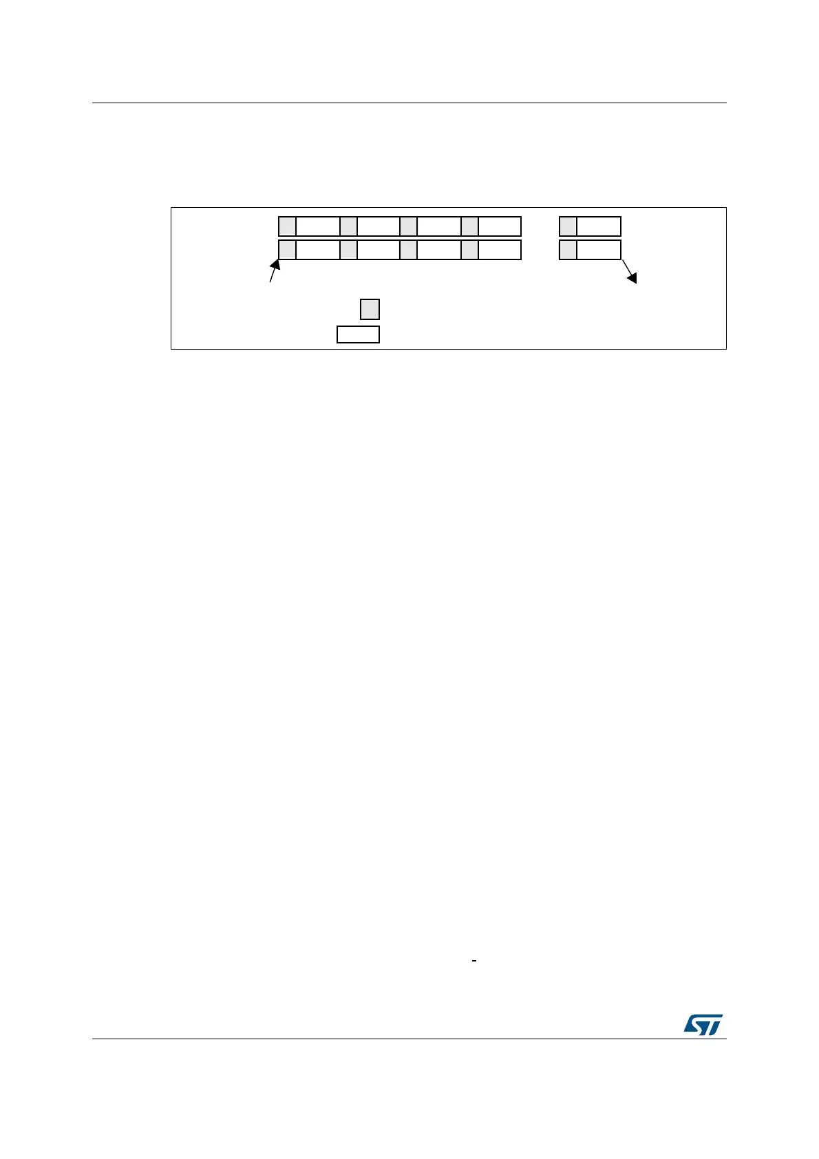
Figure 112. Regular simultaneous mode on 16 channels: dual ADC mode
If DISCEN=1 then each “n” simultaneous conversions of the regular sequence require a
regular trigger event to occur (“n” is defined by DISCNUM).
This mode can be combined with AUTDLY mode:
• Once a simultaneous conversion of the sequence has ended, the next conversion in
the sequence is started only if the common data register, ADCx_CDR (or the regular
data register of the master ADC) has been read (delay phase).
• Once a simultaneous regular sequence of conversions has ended, a new regular
trigger event is accepted only if the common data register (ADCx_CDR) has been read
(delay phase). Any new regular trigger events occurring during the ongoing regular
sequence and the associated delay phases are ignored.
It is possible to use the DMA to handle data in regular simultaneous mode combined with
AUTDLY mode, assuming that multi-DMA mode is used: bits MDMA must be set to 0b10 or
0b11.
When regular simultaneous mode is combined with AUTDLY mode, it is mandatory for the
user to ensure that:
• The number of conversions in the master’s sequence is equal to the number of
conversions in the slave’s.
• For each simultaneous conversions of the sequence, the length of the conversion of
the slave ADC is inferior to the length of the conversion of the master ADC. Note that
the length of the sequence depends on the number of channels to convert and the
sampling time and the resolution of each channels.
Note: This combination of regular simultaneous mode and AUTDLY mode is restricted to the use
case when only regular channels are programmed: it is forbidden to program injected
channels in this combined mode.
Interleaved mode with independent injected
This mode is selected by programming bits DUAL[4:0] = 00111.
This mode can be started only on a regular group (usually one channel). The external
trigger source comes from the regular channel multiplexer of the master ADC.
After an external trigger occurs:
• The master ADC starts immediately.
• The slave ADC starts after a delay of several
ADC clock cycles after the sampling
phase of the master ADC has complete.
0$67(5$'&
6/$9($'&
(QGRIUHJXODUVHTXHQFHRQ
0$67(5DQG6/$9($'&
&+
&+
DLE
6DPSOLQJ
&RQYHUVLRQ
7ULJJHU
&+
&+
&+ &+
&+
&+
&+ &+