DocID024597 Rev 3 493/1693
RM0351 Analog-to-digital converters (ADC)
540
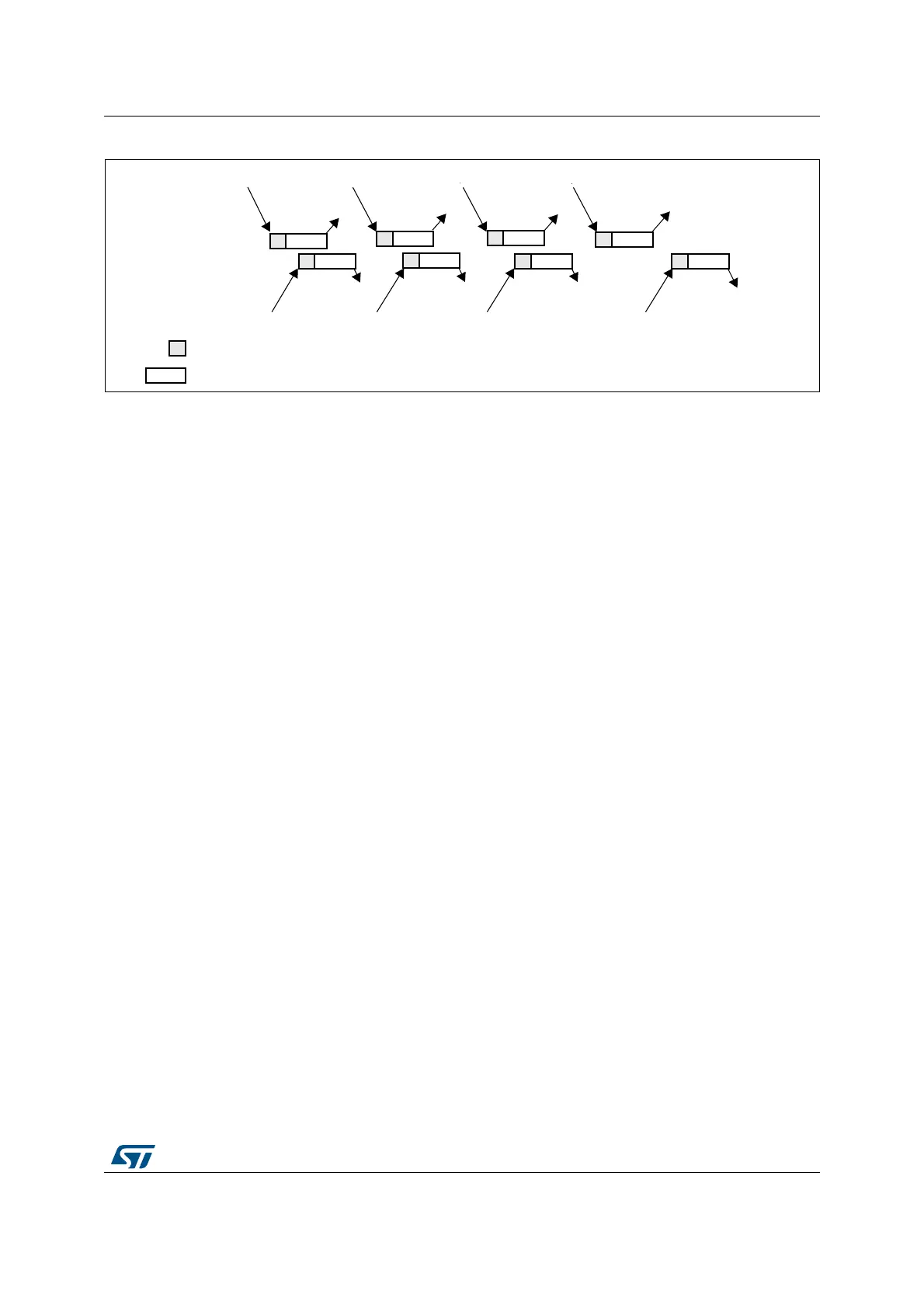
Figure 117. Alternate trigger: 4 injected channels (each ADC) in discontinuous mode
Combined regular/injected simultaneous mode
This mode is selected by programming bits DUAL[4:0] = 00001.
It is possible to interrupt the simultaneous conversion of a regular group to start the
simultaneous conversion of an injected group.
Note: In combined regular/injected simultaneous mode, one must convert sequences with the
same length or ensure that the interval between triggers is longer than the long conversion
time of the 2 sequences. Otherwise, the ADC with the shortest sequence may restart while
the ADC with the longest sequence is completing the previous conversions.
Combined regular simultaneous + alternate trigger mode
This mode is selected by programming bits DUAL[4:0]=00010.
It is possible to interrupt the simultaneous conversion of a regular group to start the alternate
trigger conversion of an injected group. Figure 118 shows the behavior of an alternate
trigger interrupting a simultaneous regular conversion.
The injected alternate conversion is immediately started after the injected event. If a regular
conversion is already running, in order to ensure synchronization after the injected
conversion, the regular conversion of all (master/slave) ADCs is stopped and resumed
synchronously at the end of the injected conversion.
Note: In combined regular simultaneous + alternate trigger mode, one must convert sequences
with the same length or ensure that the interval between triggers is longer than the long
conversion time of the 2 sequences. Otherwise, the ADC with the shortest sequence may
restart while the ADC with the longest sequence is completing the previous conversions.
VWWULJJHU
QGWULJJHU
UGWULJJHU
WKWULJJHU
WKWULJJHU
WKWULJJHU
WKWULJJHU
WKWULJJHU
-(2&-(26RQ
PDVWHU$'&
DL9P
0$67(5$'&
6/$9($'&
-(2&RQ
PDVWHU$'&
-(2&-(26RQ
PDVWHU$'&
-(2&RQ
PDVWHU$'&
-(2&RQ
PDVWHU$'&
-(2&RQ
PDVWHU$'&
-(2&RQ
PDVWHU$'&
-(2&RQ
PDVWHU$'&
6DPSOLQJ
&RQYHUVLRQ

 Loading...


