General-purpose timers (TIM15/16/17) RM0351
992/1693 DocID024597 Rev 3
28.6.4 TIM16&TIM17 status register (TIMx_SR)
Address offset: 0x10
Reset value: 0x0000
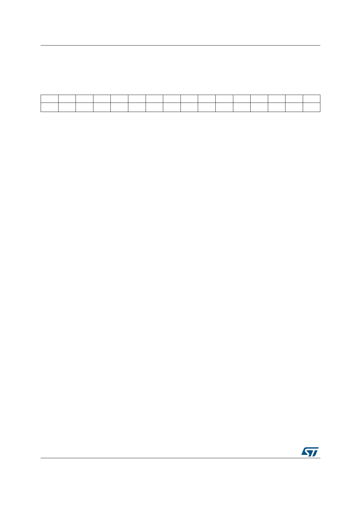
1514131211109876543210
Res Res Res Res Res Res CC1OF Res BIF Res COMIF Res Res Res CC1IF UIF
rc_w0 rc_w0
rc_w0
rc_w0 rc_w0
Bits 15:10 Reserved, must be kept at reset value.
Bit 9 CC1OF: Capture/Compare 1 overcapture flag
This flag is set by hardware only when the corresponding channel is configured in input
capture mode. It is cleared by software by writing it to ‘0’.
0: No overcapture has been detected
1: The counter value has been captured in TIMx_CCR1 register while CC1IF flag was
already set
Bit 8 Reserved, must be kept at reset value.
Bit 7 BIF: Break interrupt flag
This flag is set by hardware as soon as the break input goes active. It can be cleared by
software if the break input is not active.
0: No break event occurred
1: An active level has been detected on the break input
Bit 6 Reserved, must be kept at reset value.
Bit 5 COMIF: COM interrupt flag
This flag is set by hardware on a COM event (once the capture/compare control bits –CCxE,
CCxNE, OCxM– have been updated). It is cleared by software.
0: No COM event occurred
1: COM interrupt pending
Bits 4:2 Reserved, must be kept at reset value.
Bit 1 CC1IF: Capture/Compare 1 interrupt flag
If channel CC1 is configured as output:
This flag is set by hardware when the counter matches the compare value. It is cleared by
software.
0: No match.
1: The content of the counter TIMx_CNT matches the content of the TIMx_CCR1 register.
When the contents of TIMx_CCR1 are greater than the contents of TIMx_ARR, the CC1IF
bit goes high on the counter overflow
If channel CC1 is configured as input:
This bit is set by hardware on a capture. It is cleared by software or by reading the
TIMx_CCR1 register.
0: No input capture occurred
1: The counter value has been captured in TIMx_CCR1 register (An edge has been
detected on IC1 which matches the selected polarity)