Serial audio interface (SAI) RM0351
1346/1693 DocID024597 Rev 3
39.5 SAI registers
39.5.1 Global configuration register (SAI_GCR)
Address offset: 0x00
Reset value: 0x0000 0000
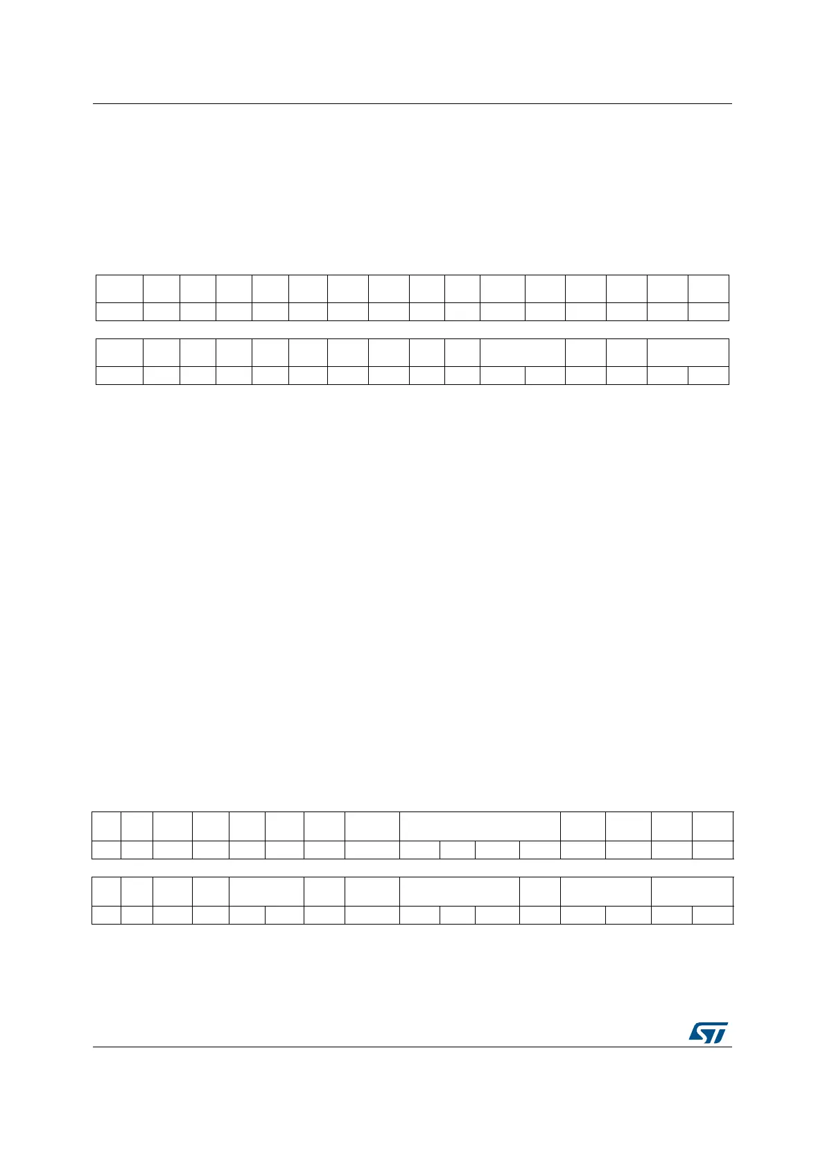
39.5.2 Configuration register 1 (SAI_ACR1 / SAI_BCR1)
Address offset: Block A: 0x004
Address offset: Block B: 0x024
Reset value: 0x0000 0040
31 30 29 28 27 26 25 24 23 22 21 20 19 18 17 16
Res. Res. Res. Res. Res. Res. Res. Res. Res. Res. Res. Res. Res. Res. Res. Res.
15 14 13 12 11 10 9 8 7 6 5 4 3 2 1 0
Res. Res. Res. Res. Res. Res. Res. Res. Res. Res. SYNCOUT[1:0] Res. Res. SYNCIN[1:0]
rw rw rw rw
Bits 31:6 Reserved, always read as 0.
Bits 5:4 SYNCOUT[1:0]: Synchronization outputs
These bits are set and cleared by software.
00: No synchronization output signals. SYNCOUT[1:0] should be configured as No synchronization
output signals when audio block is configured as SPDIF
01: Block A used for further synchronization for others SAI
10: Block B used for further synchronization for others SAI
11: Reserved. These bits must be set when both audio block (A and B) are disabled.
Bits 3:2 Reserved, always read as 0.
Bits 1:0 SYNCIN[1:0]: Synchronization inputs
These bits are set and cleared by software.
Please refer to for information on how to program this field.
These bits must be set when both audio blocks (A and B) are disabled.
They are meaningful if one of the two audio block is defined to operate in synchronous mode with an
external SAI (SYNCEN[1:0] = 01 in SAI_ACR1 or in SAI_BCR1 registers).
31 30 29 28 27 26 25 24 23 22 21 20 19 18 17 16
Res. Res. Res. Res. Res. Res. Res. Res. MCKDIV[3:0] NODIV Res. DMAEN
SAIX
EN
rw rw rw rw rw rw rw
15 14 13 12 11 10 9 8 7 6 5 4 3 2 1 0
Res. Res.
OUTD
RIV
MONO SYNCEN[1:0] CKSTR LSBFIRST DS[2:0] Res. PRTCFG[1:0] MODE[1:0]
rw rw rw rw rw rw rw rw rw rw rw rw rw

 Loading...


