Advanced-control timers (TIM1/TIM8) RM0351
802/1693 DocID024597 Rev 3
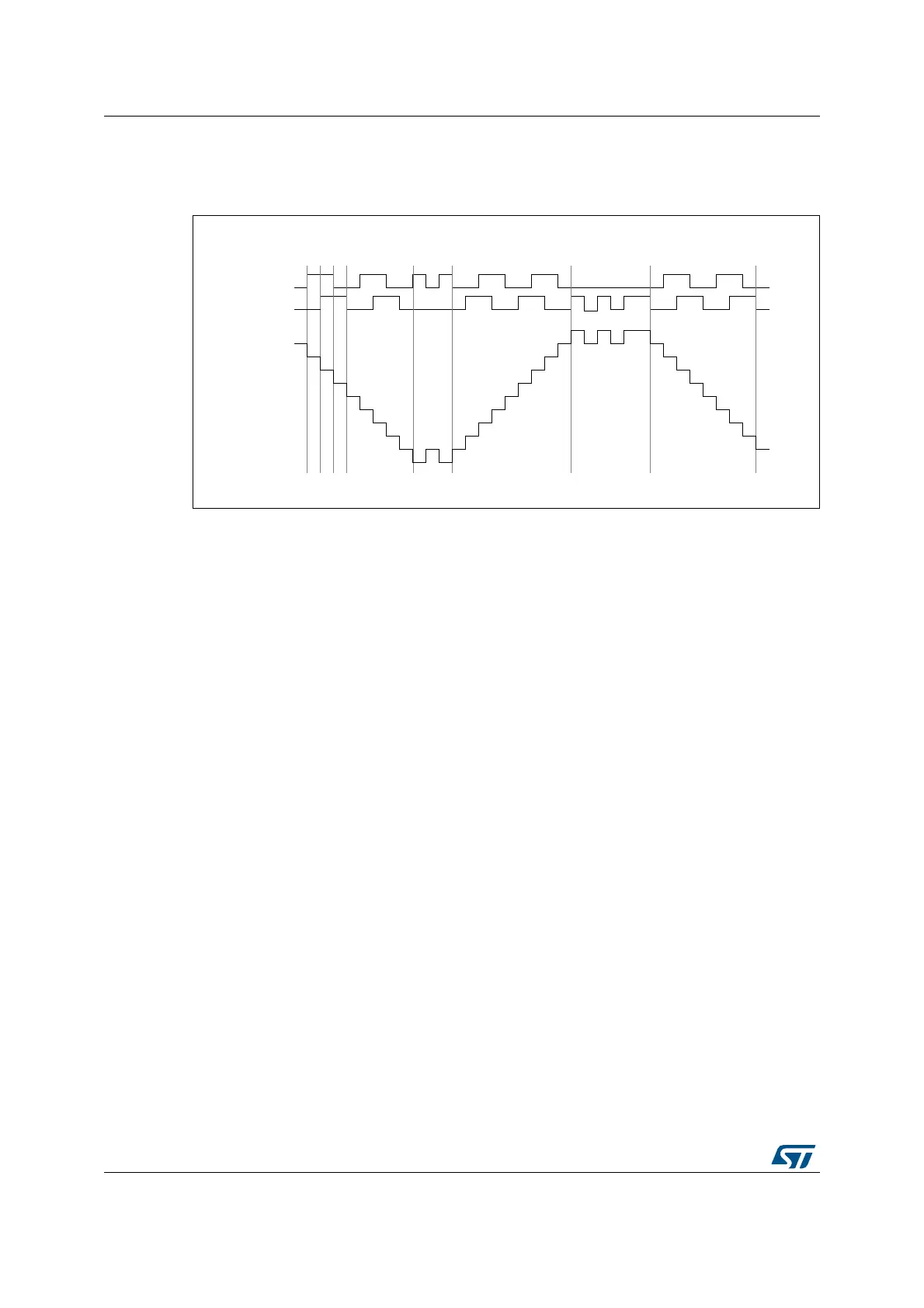
Figure 242 gives an example of counter behavior when TI1FP1 polarity is inverted (same
configuration as above except CC1P=’1’).
Figure 242. Example of encoder interface mode with TI1FP1 polarity inverted.
The timer, when configured in Encoder Interface mode provides information on the sensor’s
current position. You can obtain dynamic information (speed, acceleration, deceleration) by
measuring the period between two encoder events using a second timer configured in
capture mode. The output of the encoder which indicates the mechanical zero can be used
for this purpose. Depending on the time between two events, the counter can also be read
at regular times. You can do this by latching the counter value into a third input capture
register if available (then the capture signal must be periodic and can be generated by
another timer). when available, it is also possible to read its value through a DMA request.
The IUFREMAP bit in the TIMx_CR1 register forces a continuous copy of the update
interrupt flag (UIF) into the timer counter register’s bit 31 (TIMxCNT[31]). This allows both
the counter value and a potential roll-over condition signaled by the UIFCPY flag to be read
in an atomic way. It eases the calculation of angular speed by avoiding race conditions
caused, for instance, by a processing shared between a background task (counter reading)
and an interrupt (update interrupt).
There is no latency between the UIF and UIFCPY flag assertions.
In 32-bit timer implementations, when the IUFREMAP bit is set, bit 31 of the counter is
overwritten by the UIFCPY flag upon read access (the counter’s most significant bit is only
accessible in write mode).
26.3.23 UIF bit remapping
The IUFREMAP bit in the TIMx_CR1 register forces a continuous copy of the Update
Interrupt Flag UIF into the timer counter register’s bit 31 (TIMxCNT[31]). This allows both
the counter value and a potential roll-over condition signaled by the UIFCPY flag to be read
in an atomic way. In particular cases, it can ease the calculations by avoiding race
conditions, caused for instance by a processing shared between a background task
(counter reading) and an interrupt (Update Interrupt).
There is no latency between the UIF and UIFCPY flags assertion.
7,
EDFNZDUGMLWWHU MLWWHU
XSGRZQ
7,
&RXQWHU
IRUZDUG IRUZDUG
069
GRZQ