DocID024597 Rev 3 613/1693
RM0351 Digital filter for sigma delta modulators (DFSDM)
657
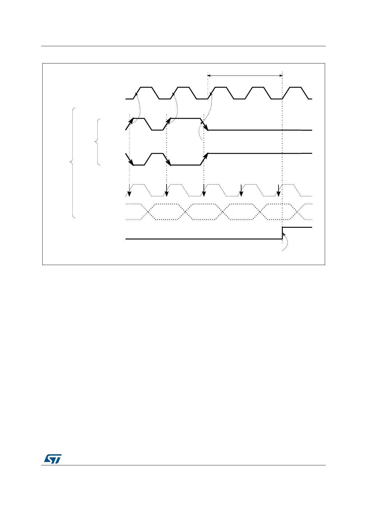
Figure 149. Clock absence timing diagram for Manchester coding
Manchester/SPI code synchronization
The Manchester coded stream must be synchronized the first time after enabling the
channel (CHEN=1 in DFSDM_CHCFGyR1 register). The synchronization ends when a data
transition from 0 to 1 or from 1 to 0 (to be able to detect valid data edge) is received. The
end of the synchronization can be checked by polling CKABF[y]=0 for a given channel after
it has been cleared by CLRCKABF[y] in DFSDMx_ICR, following the software sequence
detailed hereafter:
CKABF[y] flag is cleared by setting CLRCKABF[y] bit. If channel y is not yet synchronized
the hardware immediately set the CKABF[y] flag. Software is then reading back the
CKABF[y] flag and if it is set then perform again clearing of this flag by setting
CLRCKABF[y] bit. This software sequence (polling of CKABF[y] flag) continues until
CKABF[y] flag is set (signalizing that Manchester stream is synchronized). To be able to
synchronize/receive Manchester coded data the CKOUTDIV divider (in
DFSDM_CHCFG0R1 register) must be set with respect to expected Manchester data rate
according the formula below.
')6'0B&.287
UHFRYHUHGFORFN
6,73
')6'0B'$7,1\
6,73
0DQFKHVWHUFORFNSUHVHQFH
WLPLQJ
UHFRYHUHGGDWD
""
ODVWGDWDFKDQJH
&.$%)>\@
HUURUUHSRUWHG
UHVWDUWFRXQWLQJ
PD[SHULRGV
069
CKOUTDIV 1+()T
SYSCLK
×()T
Manchester clock
2 CKOUTDIV× T
SYSCLK
×()<<