Universal synchronous asynchronous receiver transmitter (USART) RM0351
1242/1693 DocID024597 Rev 3
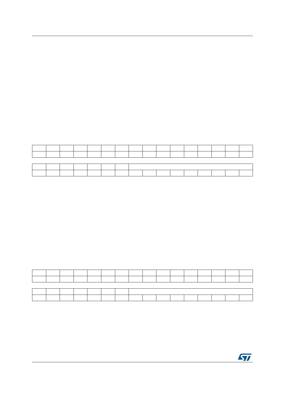
36.8.10 Receive data register (USARTx_RDR)
Address offset: 0x24
Reset value: Undefined
36.8.11 Transmit data register (USARTx_TDR)
Address offset: 0x28
Reset value: Undefined
Bit 3 ORECF: Overrun error clear flag
Writing 1 to this bit clears the ORE flag in the USARTx_ISR register.
Bit 2 NCF: Noise detected clear flag
Writing 1 to this bit clears the NF flag in the USARTx_ISR register.
Bit 1 FECF: Framing error clear flag
Writing 1 to this bit clears the FE flag in the USARTx_ISR register.
Bit 0 PECF: Parity error clear flag
Writing 1 to this bit clears the PE flag in the USARTx_ISR register.
31 30 29 28 27 26 25 24 23 22 21 20 19 18 17 16
Res. Res. Res. Res. Res. Res. Res. Res. Res. Res. Res. Res. Res. Res. Res. Res.
1514131211109876543210
Res. Res. Res. Res. Res. Res. Res. RDR[8:0]
rrrrrrrrr
Bits 31:9 Reserved, must be kept at reset value.
Bits 8:0 RDR[8:0]: Receive data value
Contains the received data character.
The RDR register provides the parallel interface between the input shift register and the
internal bus (see Figure 383).
When receiving with the parity enabled, the value read in the MSB bit is the received parity
bit.
31 30 29 28 27 26 25 24 23 22 21 20 19 18 17 16
Res. Res. Res. Res. Res. Res. Res. Res. Res. Res. Res. Res. Res. Res. Res. Res.
1514131211109876543210
Res. Res. Res. Res. Res. Res. Res. TDR[8:0]
rw rw rw rw rw rw rw rw rw

 Loading...


