Serial peripheral interface (SPI) RM0351
1286/1685 DocID024597 Rev 3
Half-duplex communication
The SPI can communicate in half-duplex mode by setting the BIDIMODE bit in the
SPIx_CR1 register. In this configuration, one single cross connection line is used to link the
shift registers of the master and slave together. During this communication, the data is
synchronously shifted between the shift registers on the SCK clock edge in the transfer
direction selected reciprocally by both master and slave with the BDIOE bit in their
SPIx_CR1 registers. In this configuration, the master’s MISO pin and the slave’s MOSI pin
are free for other application uses and act as GPIOs.
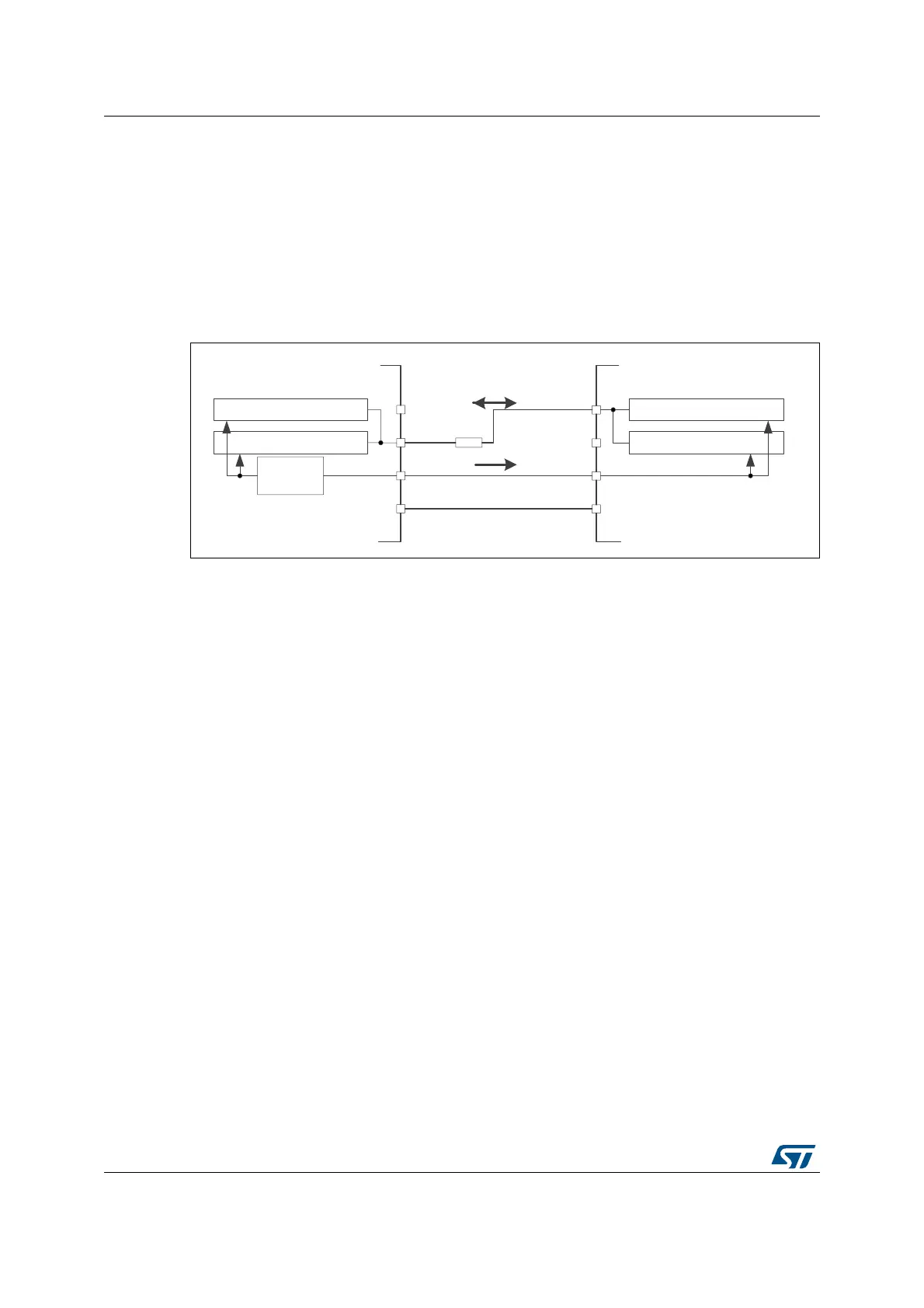
Figure 422. Half-duplex single master/ single slave application
1. The NSS pins can be used to provide a hardware control flow between master and slave. Optionally, the
pins can be left unused by the peripheral. Then the flow has to be handled internally for both master and
slave. For more details see Section 38.4.5: Slave select (NSS) pin management.
2. In this configuration, the master’s MISO pin and the slave’s MOSI pin can be used as GPIOs.
3. A critical situation can happen when communication direction is changed not synchronously between two
nodes working at bidirectionnal mode and new transmitter accesses the common data line while former
transmitter still keeps an opposite value on the line (the value depends on SPI configuration and
communication data). Both nodes then fight while providing opposite output levels on the common line
temporary till next node changes its direction settings correspondingly, too. It is suggested to insert a serial
resistance between MISO and MOSI pins at this mode to protect the outputs and limit the current blowing
between them at this situation.
Simplex communications
The SPI can communicate in simplex mode by setting the SPI in transmit-only or in receive-
only using the RXONLY bit in the SPIx_CR2 register. In this configuration, only one line is
used for the transfer between the shift registers of the master and slave. The remaining
MISO and MOSI pins pair is not used for communication and can be used as standard
GPIOs.
• Transmit-only mode (RXONLY=0): The configuration settings are the same as for full-
duplex. The application has to ignore the information captured on the unused input pin.
This pin can be used as a standard GPIO.
• Receive-only mode (RXONLY=1): The application can disable the SPI output function
by setting the RXONLY bit. In slave configuration, the MISO output is disabled and the
pin can be used as a GPIO. The slave continues to receive data from the MOSI pin
while its slave select signal is active (see 38.4.4: Multi-master communication).
Received data events appear depending on the data buffer configuration. In the master
configuration, the MOSI output is disabled and the pin can be used as a GPIO. The
clock signal is generated continuously as long as the SPI is enabled. The only way to
stop the clock is to clear the RXONLY bit or the SPE bit and wait until the incoming
pattern from the MISO pin is finished and fills the data buffer structure, depending on its
configuration.
5[VKLIWUHJLVWHU
7[VKLIWUHJLVWHU 5[VKLIWUHJLVWHU
7[VKLIWUHJLVWHU
63,FORFN
JHQHUDWRU
0DVWHU
6ODYH
0,62
026,
6&.
166
0,62
026,
6&.
166
Nȍ
06Y9

 Loading...


