DocID024597 Rev 3 775/1693
RM0351 Advanced-control timers (TIM1/TIM8)
856
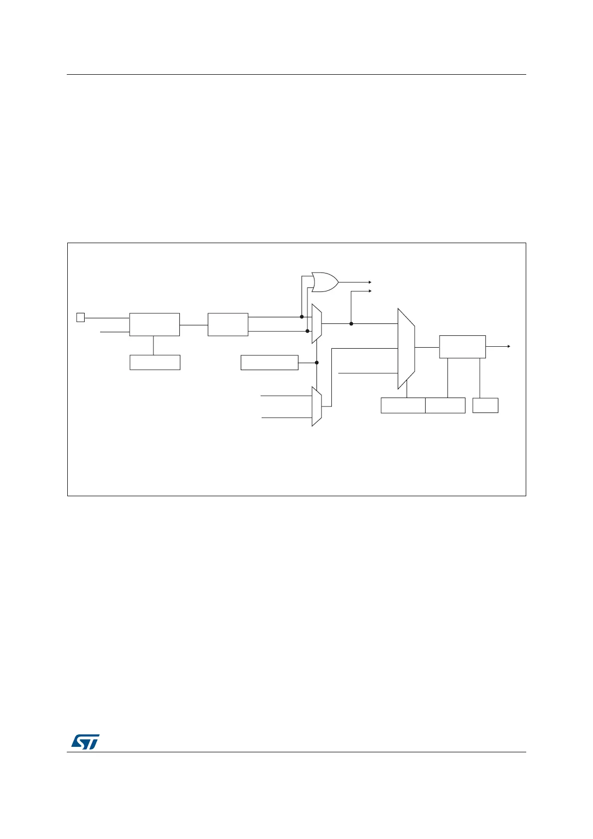
26.3.6 Capture/compare channels
Each Capture/Compare channel is built around a capture/compare register (including a
shadow register), an input stage for capture (with digital filter, multiplexing, and prescaler,
except for channels 5 and 6) and an output stage (with comparator and output control).
Figure 217 to Figure 220 give an overview of one Capture/Compare channel.
The input stage samples the corresponding TIx input to generate a filtered signal TIxF.
Then, an edge detector with polarity selection generates a signal (TIxFPx) which can be
used as trigger input by the slave mode controller or as the capture command. It is
prescaled before the capture register (ICxPS).
Figure 217. Capture/compare channel (example: channel 1 input stage)
The output stage generates an intermediate waveform which is then used for reference:
OCxRef (active high). The polarity acts at the end of the chain.
'LYLGHU
,&36>@
7,)B('
7RWKHVODYHPRGHFRQWUROOHU
7,)3
&&6>@
,&
7,)3
75&
IURPVODYHPRGH
FRQWUROOHU
,&36
069
7,
7,0[B&&(5
&&3&&13
)LOWHU
GRZQFRXQWHU
,&)>@
7,0[B&&05
(GJH
GHWHFWRU
7,)B5LVLQJ
7,)B)DOOLQJ
7,0[B&&05
7,0[B&&(5
7,)B5LVLQJ
IURPFKDQQHO
7,)B)DOOLQJ
IURPFKDQQHO
7,)
I
&&(
'76

 Loading...


