3.9.1.2 USB Power Distribution
This chip includes an internal 5 V to 3.3 V USB regulator that always powers the USB
transceiver. The regulator output may optionally be used to power the MCU VDD
(depending on the application).
3.9.1.2.1 AA/AAA cells power supply
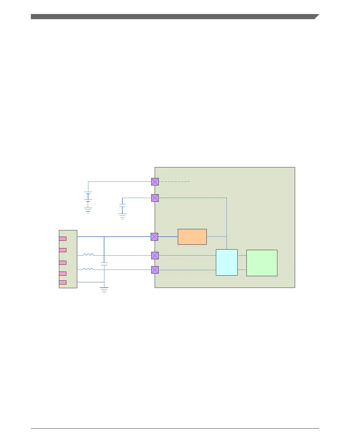
The chip can be powered by two AA/AAA cells. In this case, the MCU is powered
through VDD which is within the 1.8 to 3.0 V range. After USB cable insertion is
detected, the USB regulator is enabled to power the USB transceiver.
USB
Regulator
USB
XCVR
USB
Controller
USB0_DP
USB0_DM
VDD
VOUT33
VREGIN
TYPE A
D+
D-
VBUS
2 AA Cells
Cstab
To PMC and Pads
Chip
+
Figure 3-47. USB regulator AA cell use case
3.9.1.2.2
Li-Ion battery power supply
The chip can also be powered by a single Li-ion battery. In this case, VOUT33 is
connected to VDD. The USB regulator must be enabled by default to power the MCU.
When connected to a USB host, the input source of this regulator is switched to the USB
bus supply from the Li-ion battery.
Chapter 3 Chip Configuration
K22F Sub-Family Reference Manual, Rev. 4, 08/2016
NXP Semiconductors 123

 Loading...