UM10360 All information provided in this document is subject to legal disclaimers. © NXP B.V. 2013. All rights reserved.
User manual Rev. 3 — 19 December 2013 20 of 841
NXP Semiconductors
UM10360
Chapter 3: LPC176x/5x System control
On the assertion of a reset source external to the Cortex-M3 CPU (POR, BOD reset,
External reset, and Watchdog reset), the IRC starts up. After the IRC-start-up time
(maximum of 60 s on power-up) and after the IRC provides a stable clock output, the
reset signal is latched and synchronized on the IRC clock. Then the following two
sequences start simultaneously:
1. The 2-bit IRC wake-up timer starts counting when the synchronized reset is
de-asserted. The boot code in the ROM starts when the 2-bit IRC wake-up timer times
out. The boot code performs the boot tasks and may jump to the flash. If the flash is
not ready to access, the Flash Accelerator will insert wait cycles until the flash is
ready.
2. The flash wake-up timer (9-bit) starts counting when the synchronized reset is
de-asserted. The flash wake-up timer generates the 100 s flash start-up time. Once
it times out, the flash initialization sequence is started, which takes about 250 cycles.
When it’s done, the Flash Accelerator will be granted access to the flash.
When the internal Reset is removed, the processor begins executing at address 0, which
is initially the Reset vector mapped from the Boot Block. At that point, all of the processor
and peripheral registers have been initialized to predetermined values.
Figure 5
shows an example of the relationship between the RESET, the IRC, and the
processor status when the LPC176x/5x starts up after reset. See Section 4.3.2 “
Main
oscillator” for start-up of the main oscillator if selected by the user code.
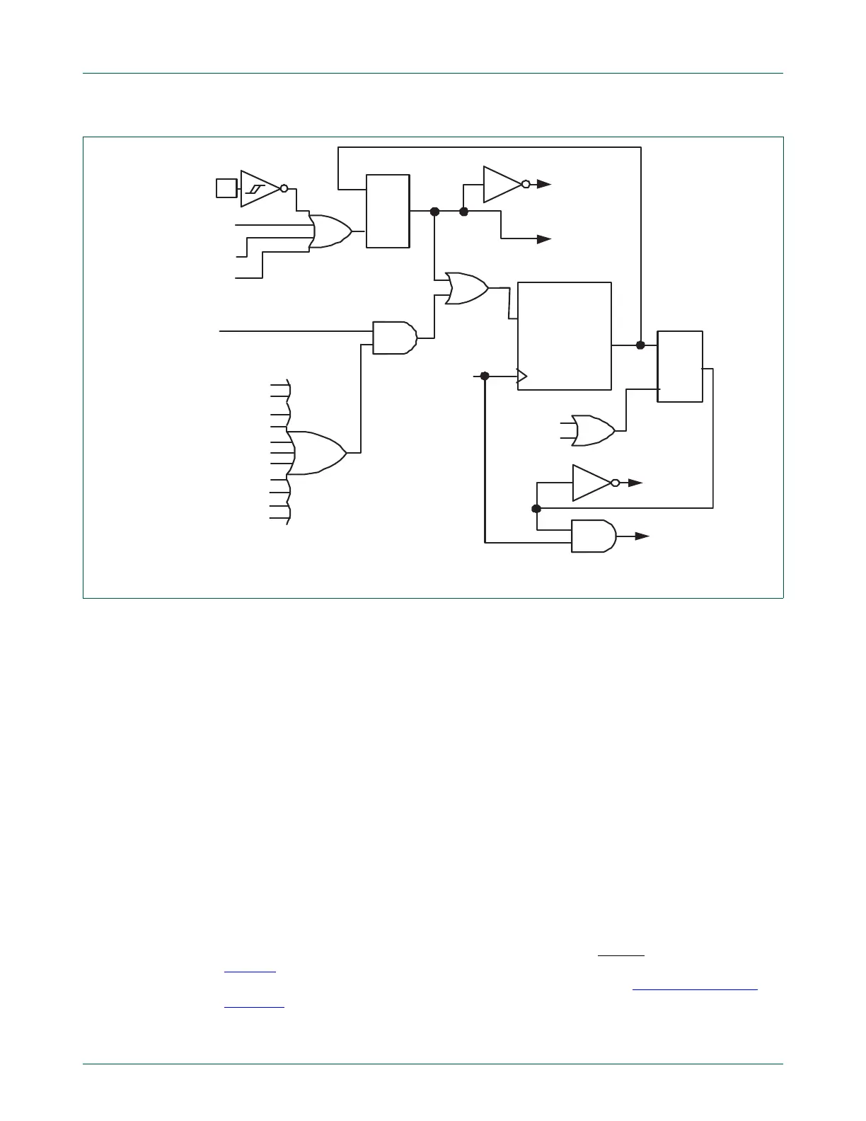
Fig 4. Reset block diagram including the wake-up timer
C
Q
S
APB read of
PDBIT
in PCON
power-down
C
Q
S
F
OSC
to other
blocks
WAKE-UP TIMER
watchdog
reset
external
reset
START
COUNT 2
n
internal RC
oscillator
Reset to the
on-chip circuitry
Reset to
PCON.PD
write “1”
from APB
reset
EINT0 wake-up
EINT1 wake-up
EINT2 wake-up
POR
BOD
EINT3 wake-up
RTC wake-up
BOD wake-up
Ethernet MAC wake-up
USB need_clk wake-up
CAN wake-up
GPIO0 port wake-up
GPIO2 port wake-up

 Loading...


