UM10360 All information provided in this document is subject to legal disclaimers. © NXP B.V. 2013. All rights reserved.
User manual Rev. 3 — 19 December 2013 325 of 841
NXP Semiconductors
UM10360
Chapter 15: LPC176x/5x UART1
interrupt handler routine can determine the cause of the interrupt and how to clear the
active interrupt. The U1IIR must be read in order to clear the interrupt prior to exiting the
Interrupt Service Routine.
The UART1 RLS interrupt (U1IIR[3:1] = 011) is the highest priority interrupt and is set
whenever any one of four error conditions occur on the UART1RX input: overrun error
(OE), parity error (PE), framing error (FE) and break interrupt (BI). The UART1 Rx error
condition that set the interrupt can be observed via U1LSR[4:1]. The interrupt is cleared
upon an U1LSR read.
The UART1 RDA interrupt (U1IIR[3:1] = 010) shares the second level priority with the CTI
interrupt (U1IIR[3:1] = 110). The RDA is activated when the UART1 Rx FIFO reaches the
trigger level defined in U1FCR7:6 and is reset when the UART1 Rx FIFO depth falls below
the trigger level. When the RDA interrupt goes active, the CPU can read a block of data
defined by the trigger level.
The CTI interrupt (U1IIR[3:1] = 110) is a second level interrupt and is set when the UART1
Rx FIFO contains at least one character and no UART1 Rx FIFO activity has occurred in
3.5 to 4.5 character times. Any UART1 Rx FIFO activity (read or write of UART1 RSR) will
clear the interrupt. This interrupt is intended to flush the UART1 RBR after a message has
been received that is not a multiple of the trigger level size. For example, if a peripheral
wished to send a 105 character message and the trigger level was 10 characters, the
CPU would receive 10 RDA interrupts resulting in the transfer of 100 characters and 1 to 5
CTI interrupts (depending on the service routine) resulting in the transfer of the remaining
5 characters.
[1] Values "0000", “0011”, “0101”, “0111”, “1000”, “1001”, “1010”, “1011”,”1101”,”1110”,”1111” are reserved.
[2] For details see Section 15.4.10 “
UART1 Line Status Register (U1LSR - 0x4001 0014)”
[3] For details see Section 15.4.1 “UART1 Receiver Buffer Register (U1RBR - 0x4001 0000, when DLAB = 0)”
[4] For details see Section 15.4.5 “UART1 Interrupt Identification Register (U1IIR - 0x4001 0008)” and
Section 15.4.2 “
UART1 Transmitter Holding Register (U1THR - 0x4001 0000 when DLAB = 0)”
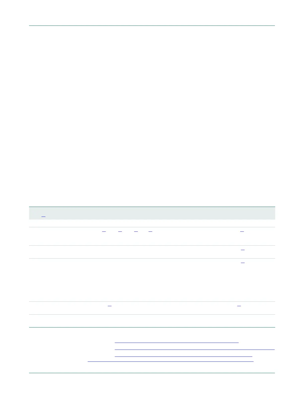
Table 296: UART1 Interrupt Handling
U1IIR[3:0]
value
[1]
Priority Interrupt
Type
Interrupt Source Interrupt Reset
0001 - None None -
0110 Highest RX Line
Status /
Error
OE
[2]
or PE
[2]
or FE
[2]
or BI
[2]
U1LSR Read
[2]
0100 Second RX Data
Available
Rx data available or trigger level reached in FIFO
(U1FCR0=1)
U1RBR Read
[3]
or UART1
FIFO drops below trigger level
1100 Second Character
Time-out
indication
Minimum of one character in the RX FIFO and no
character input or removed during a time period depending
on how many characters are in FIFO and what the trigger
level is set at (3.5 to 4.5 character times).
The exact time will be:
[(word length)
7 - 2] 8 + [(trigger level - number of
characters)
8 + 1] RCLKs
U1RBR Read
[3]
0010 Third THRE THRE
[2]
U1IIR Read
[4]
(if source of
interrupt) or THR write
0000 Fourth Modem
Status
CTS or DSR or RI or DCD MSR Read

 Loading...


