UM10360 All information provided in this document is subject to legal disclaimers. © NXP B.V. 2013. All rights reserved.
User manual Rev. 3 — 20 December 2013 731 of 841
NXP Semiconductors
UM10360
Chapter 34: Appendix: Cortex-M3 user guide
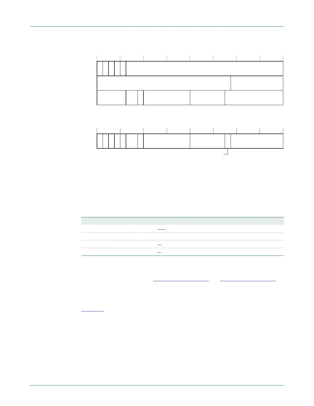
The PSR bit assignments are:
Access these registers individually or as a combination of any two or all three registers,
using the register name as an argument to the
MSR
or
MRS
instructions. For example:
• read all of the registers using
PSR
with the
MRS
instruction
• write to the APSR using
APSR
with the
MSR
instruction.
The PSR combinations and attributes are:
[1] The processor ignores writes to the IPSR bits.
[2] Reads of the EPSR bits return zero, and the processor ignores writes to the these bits
See the instruction descriptions Section 34.2.10.6 “MRS” and Section 34.2.10.7 “MSR” for
more information about how to access the program status registers.
Application Program Status Register: The APSR contains the current state of the
condition flags from previous instruction executions. See the register summary in
Table 626
for its attributes. The bit assignments are:
5HVHUYHG ,65B180%(5
1=&9
5HVHUYHG
$365
,365
(365
5HVHUYHG 5HVHUYHG
5HVHUYHG,&,,7 ,&,,77
4
Table 627. PSR register combinations
Register Type Combination
PSR RW
[1][2]
APSR, EPSR, and IPSR
IEPSR RO EPSR and IPSR
IAPSR RW
[1]
APSR and IPSR
EAPSR RW
[2]
APSR and EPSR
1
= & 9 4 ,&,,7 7 5HVHUYHG ,&,,7 ,65B180%(5
5HVHUYHG

 Loading...


