2. Indicates the NVIC's ISER, ICER, ISPR, ICPR, and IABR register number used for this IRQ. The equation to calculate this
value is: IRQ div 32
3. Indicates the NVIC's IPR register number used for this IRQ. The equation to calculate this value is: IRQ div 4
4. This interrupt can only be pended or cleared via the NVIC registers.
3.2.2.3.1 Determining the bitfield and register location for configuring a
particular interrupt
Suppose you need to configure the low-power timer (LPTMR) interrupt. The following
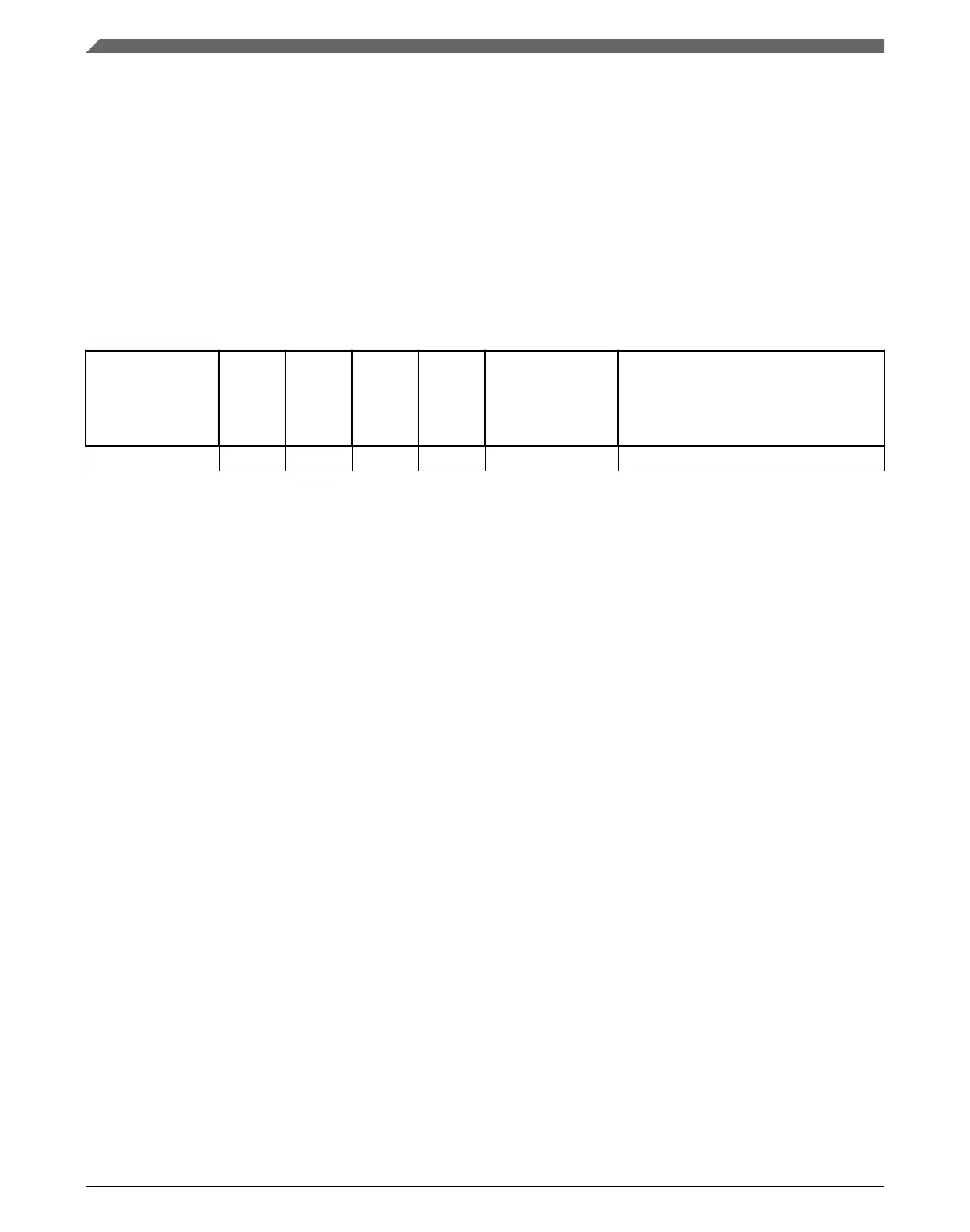
table is an excerpt of the LPTMR row from Interrupt channel assignments.
Table 3-5. LPTMR interrupt vector assignment
Address Vector IRQ
1
NVIC
non-IPR
register
number
2
NVIC
IPR
register
number
3
Source module Source description
0x0000_0128 74 58 1 14 Low Power Timer —
1. Indicates the NVIC's interrupt source number.
2. Indicates the NVIC's ISER, ICER, ISPR, ICPR, and IABR register number used for this IRQ. The equation to calculate this
value is: IRQ div 32
3. Indicates the NVIC's IPR register number used for this IRQ. The equation to calculate this value is: IRQ div 4
• The NVIC registers you would use to configure the interrupt are:
• NVICISER1
• NVICICER1
• NVICISPR1
• NVICICPR1
• NVICIABR1
• NVICIPR14
• To determine the particular IRQ's bitfield location within these particular registers:
• NVICISER1, NVICICER1, NVICISPR1, NVICICPR1, NVICIABR1 bit
location = IRQ mod 32 = 26
• NVICIPR14 bitfield starting location = 8 * (IRQ mod 4) + 4 = 20
Since the NVICIPR bitfields are 4-bit wide (16 priority levels), the NVICIPR14
bitfield range is 20-23
Therefore, the following bitfield locations are used to configure the LPTMR interrupts:
• NVICISER1[26]
• NVICICER1[26]
• NVICISPR1[26]
• NVICICPR1[26]
• NVICIABR1[26]
• NVICIPR14[23:20]
Core modules
K22F Sub-Family Reference Manual, Rev. 4, 08/2016
64 NXP Semiconductors

 Loading...