C4.2 Cross-trigger inputs and outputs
Outputs from the PMU, the ETM, and the debug subsystem are cross-trigger inputs to the processor CTI.
The CTI then generates cross-trigger outputs to other components in the SoC.
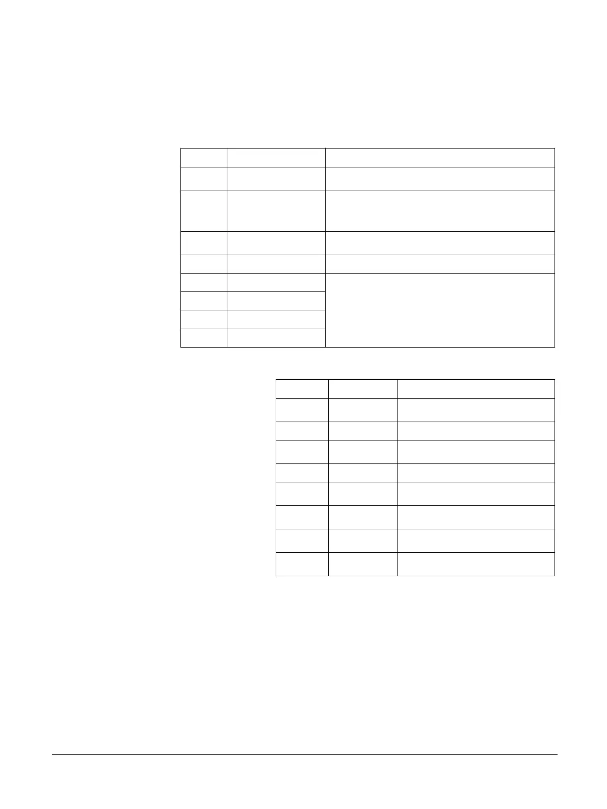
Table C4-1 Cross-trigger inputs
CTI input Name Description
0 DBGTRIGGER, pulsed
Pulsed on entry to debug state.
1 PMUIRQ
PMU-generated interrupt.
This signal is the same as nPMUIRQ with inverted polarity.
2 -
-
3 - -
4 EXTOUT[0]
Output from the ETM unit of Core<N>.
5 EXTOUT[1]
6 EXTOUT[2]
7 EXTOUT[3]
Table C4-2 Cross-trigger outputs
CTI output Name Description
0 EDBGRQ
Causes the processor to enter debug state
1 DBGRESTART Causes the processor to exit debug state
2 CTIIRQ
CTI interrupt
3 - -
4 EXTIN[0]
ETM trace unit external input
5 EXTIN[1]
ETM trace unit external input
6 EXTIN[2]
ETM trace unit external input
7 EXTIN[3]
ETM trace unit external input
C4 CTI
C4.2 Cross-trigger inputs and outputs
100236_0100_00_en Copyright © 2015–2017, 2019 Arm Limited or its affiliates. All rights
reserved.
C4-605
Non-Confidential