C11.51 Integration Instruction ATB Data Register
The TRCITIDATAR characteristics are:
Purpose
Sets the state of the ATDATAMn output pins shown in the following table.
Usage constraints
• Available when bit[0] of TRCITCTRL is set to 1.
• The value of the register sets the signals on the output pins when the register is written.
Configurations
Available in all configurations.
Attributes
See C11.1 ETM register summary on page C11-733.
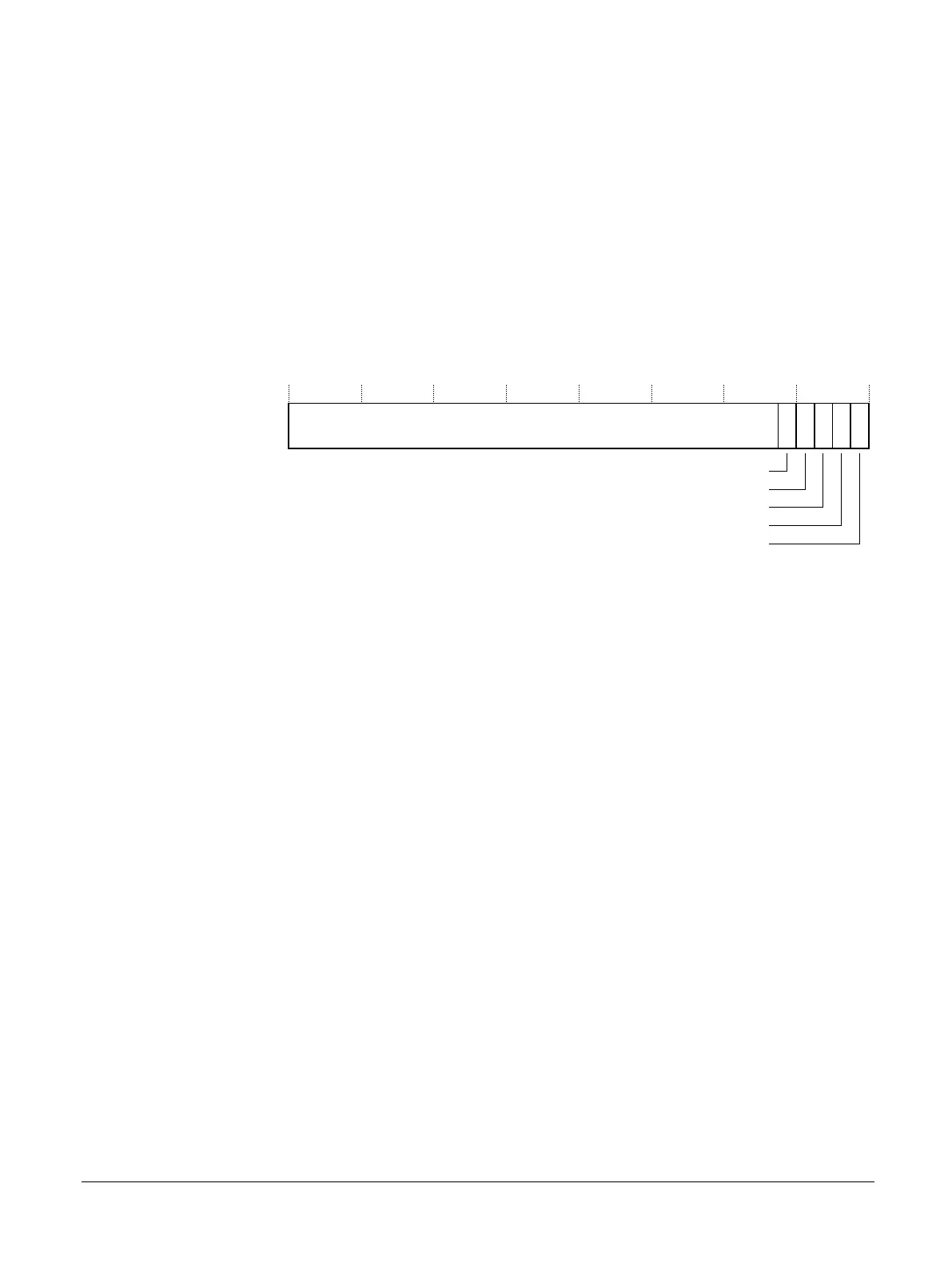
31 1 0
RES0
ATDATAM[31]
2345
ATDATAM[23]
ATDATAM[15]
ATDATAM[7]
ATDATAM[0]
Figure C11-50 TRCITIDATAR bit assignments
For all non-reserved bits:
• When a bit is set to 0, the corresponding output pin is LOW.
• When a bit is set to 1, the corresponding output pin is HIGH.
• The TRCITDDATAR bit values correspond to the physical state of the output pins.
[31:5]
Reserved, RES0.
ATDATAM[31], [4]
Drives the ATDATAM[31] output.
ATDATAM[23], [3]
Drives the ATDATAM[23] output.
ATDATAM[15], [2]
Drives the ATDATAM[15] output.
ATDATAM[7], [1]
Drives the ATDATAM[7] output.
ATDATAM[0], [0]
Drives the ATDATAM[0] output.
The TRCITIDATAR can be accessed through the external debug interface, offset 0xEEC.
C11 ETM registers
C11.51 Integration Instruction ATB Data Register
100236_0100_00_en Copyright © 2015–2017, 2019 Arm Limited or its affiliates. All rights
reserved.
C11-798
Non-Confidential