Table A3-1 Valid reset combinations (continued)
Reset combination Signals Value Description
MBIST reset
nCPUPORESET[CN:0]
nCORERESET[CN:0]
nPRESETDBG
nL2RESET
nMBISTRESET
all = 1
all = 1
1
1
0
All logic is held in reset.
Normal state
nCPUPORESET[CN:0]
nCORERESET[CN:0]
nPRESETDBG
nL2RESET
nMBISTRESET
all = 1
all = 1
1
1
1
No logic is held in reset.
Warm reset
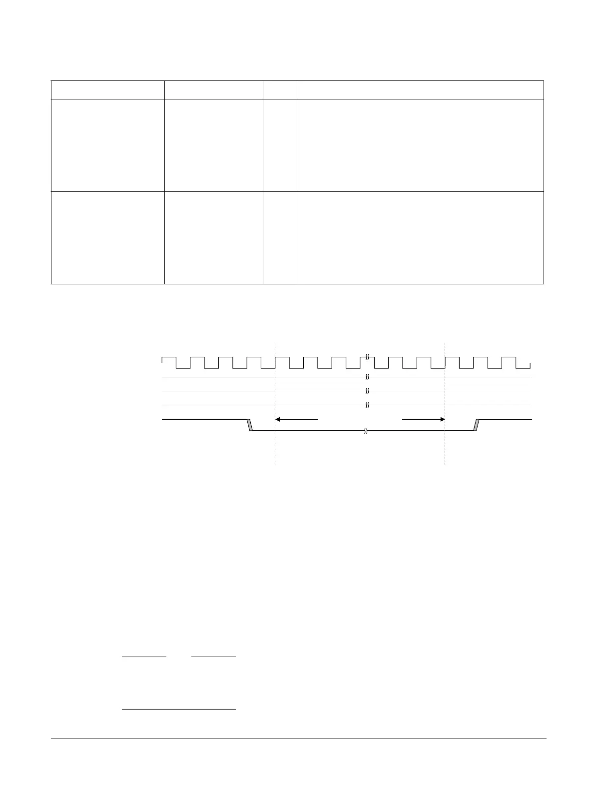
The following figure shows the Warm reset sequence for the Cortex‑A35 processor.
CLK
nCPUPORESET[N:0]
nPRESETDBG
nCORERESET[N:0]
nL2RESET
3 CLK cycles minimum
Figure A3-1 Warm reset timing
Individual core Warm reset initializes all logic in a single core apart from its Debug, ETM, breakpoint,
and watchpoint logic. Breakpoints and watchpoints for that core are retained. You must apply the correct
sequence before applying Warm reset to that core.
For individual processor Warm reset:
• You must apply steps 1 to 6 in the core powerdown sequence, see A4.6 Powering down an individual
core on page A4-65, and wait until STANDBYWFI is asserted, indicating that the core is idle,
before asserting nCORERESET for that core.
• nCORERESET for that core must assert for at least 3 CLK cycles.
• nL2RESET must not assert while any individual core is active.
• nPRESETDBG must not assert while any individual core is actively being debugged in normal
operating mode.
Note
If core dynamic retention using the CPU Q-channel interface is used, the core must be in quiescent state
with STANDBYWFI asserted and CPUQREQn, CPUQACCEPTn, and CPUQACCEPT must be
LOW before nCORERESET is applied.
A3 Clocks, Resets, and Input Synchronization
A3.3 Resets
100236_0100_00_en Copyright © 2015–2017, 2019 Arm Limited or its affiliates. All rights
reserved.
A3-54
Non-Confidential