Diagnostic aids 3-93
5058-030
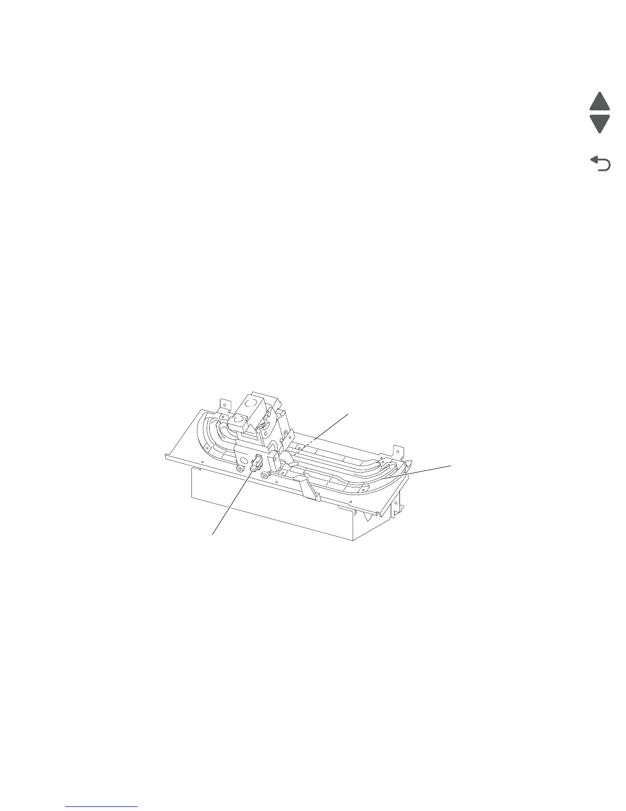
Functions of stapler sensors/motors
• Sensor (stapler carriage HP)
– A photo-interrupter sensor that detects the stapler home position, rear staple (corner) position, and rear
staple (straight) position.
– It turns high (+5 V dc) (light blocking) when the stapler comes to the specified position.
• Stapler carriage motor assembly
– A stepping motor that moves the stapler unit assembly.
– Clockwise rotation of this motor moves the stapler unit assembly to the rear side, while counterclockwise
rotation moves the stapler unit assembly to the front side.
• Sensor (low staple) in the stapler unit assembly
– A photo-interrupter sensor that detects when the stapler unit assembly is nearly out of staples.
– It turns high (+5 V dc) when 20 staples are left.
• Sensor (self priming) in the stapler unit assembly
– A photo-interrupter sensor that detects that staples are at the stapler unit assembly end; it also detects
failure in stapling.
– It turns low (0 V dc) (light blocking) when stapling is ready.
• Sensor (staple home) in the stapler unit assembly
– A photo-interrupter sensor that detects the stapler unit assembly home position; it also detects failure in
stapling.
– This sensor also functions as a trigger to stop the staple motor.
– It turns low (0 V dc) (light blocking) while the stapler unit assembly stays at the home position.
• Stapler unit motor (in the stapler unit assembly)
– A DC motor to activate the stapler unit assembly for stapling.
– Clockwise rotation of this motor enables stapling, while counterclockwise rotation returns the stapler unit
assembly.
Booklet Operation
The booklet media entrance roll assembly driven by the booklet media entrance drive motor will deliver media
from the finisher entrance and stack it against the booklet end guide in the booklet unit. When the booklet end
guide is at the bottom of the booklet unit it will continue to accept media. Once the proper amount of media is
reached, stapling will occur and booklets will be delivered in sets to the booklet media bin.
The booklet media exit roll assembly is driven by booklet folding/exit drive motor assembly and delivers booklets
to the booklet media bin. During printing, paper drawn to the booklet compiler is aligned by the booklet paddle
shaft assembly which is driven by booklet paddle shaft drive Motor.
When a sheet of paper enters the booklet compiler, tamping operation is performed by two moving tampers
moving towards the front and rear. The front tamper is driven by front booklet tamper drive motor; rear booklet
tamper drive motor. Tamping operation will be performed a final time after the last sheet is received.
Sensor (stapler carriage HP)
Stapler carriage motor asm
Stapler
rack gear