4-304 Service Manual
5058-030
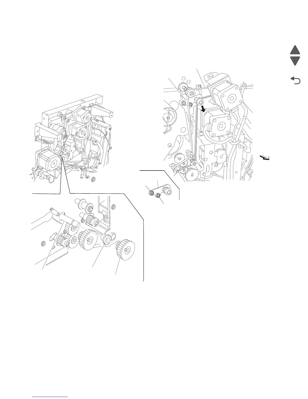
Reinstallation notes:
• The tension of the belt (exit) (F) is automatically adjusted by the force of the spring attached to the belt
tensioner bracket (D).
• Tighten the two screws in the order shown.
Punch carriage assembly removal
1. Open the finisher front door assembly.
2. Remove the rear upper cover. See “Rear upper cover removal” on page 4-309.
3. Remove the upper media bin assembly. See “Upper media bin assembly removal” on page 4-352.
4. Remove the connector from the sensor (punch carriage shift HP) (A).
5. Remove the top cover. See “Top cover removal” on page 4-351.
6. Release the harness from the punch carriage assembly (B).
7. Remove the connector from the punch carriage shift motor assembly (C).
8. Release the two punch unit assembly harnesses from the three clamps on the rear of the finisher.
9. Disconnect the two punch unit assembly harnesses from the main harness.
10. Remove the screw securing the grounding wire (D) to the punch unit carriage assembly (B).
D
F
Rear
DTighten
second
Tighten first