Plug/Jack and Wiring Diagrams
Xerox Internal Use Only Phaser 7100 Service Manual 7-49
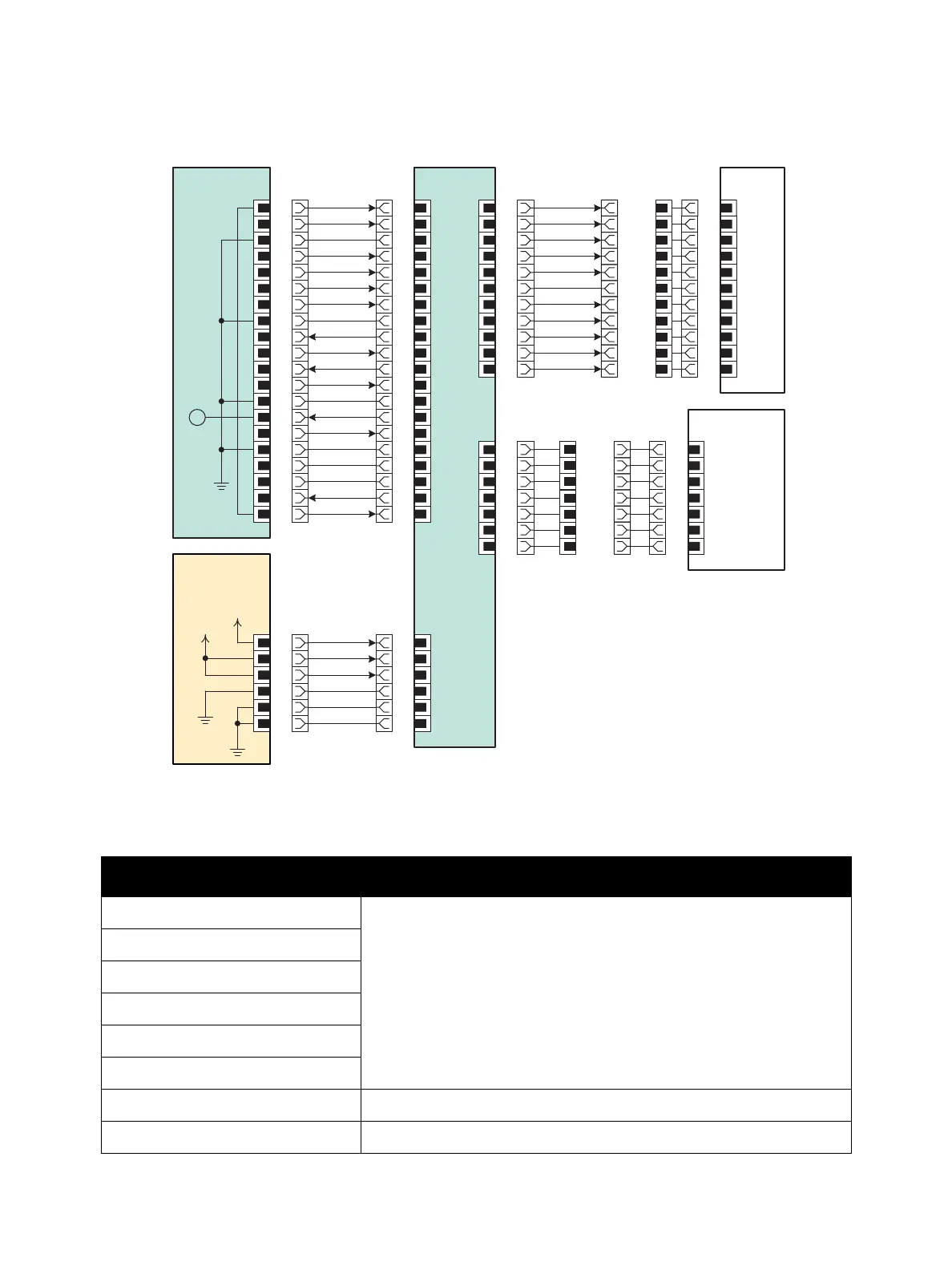
Controller
Controller Signal Lines
Signal Line Name Description
Loop 1
Controller Control signal
Line Sync
P Sync Y
P Sync M
P Sync C
P Sync K
Test Print Print Execution signal
CMD Ready Controller Control signal
MCU PWB
LVPS PWB
P/J470
1
2
3
4
5
6
7
8
STBY
+5VDC
+24VDC
I/P PWB
9
10
11
12
13
14
15
16
17
18
19
20
P/J304
20
19
18
17
16
15
14
13
12
11
10
9
8
7
6
5
4
3
2
1
P/J305
1
2
3
4
5
6
7
8
9
10
11
P/J526
6
5
4
3
2
1
P/J306
7
6
5
4
3
2
1
P/J300
6
5
4
3
2
1
J4021
11
1
210
3
4
9
8
57
66
75
4 8
93
10
11
2
1
SG
SG
SG
SG
P/J402
11
10
9
8
7
6
5
4
ROS
Assembly
3
2
1
SG
Loop2
Loop1
/Y Data
Y Data
/M Data
M Data
/C Data
C Data
/K Data
K Data
LOOP1
J101
1
P101
7
6 2
5
4
3
4
3 5
2 6
1 7
P/J102
7
6
5
4
3
2
1
SG
SG
Rtn
ESS +5VDC
ESS +5VDC
+24VDC
Control Panel
A
To AC
Power
Line Sync
P Sync Y
P Sync M
P Sync C
P Sync K
Test Print
CMD Ready
Command
Status
RLY PWR ON
PWR STS
Reserve
N.C.
Reset
Loop2
s7100-306

 Loading...


